This electronic board, now in its third generation, deals with the control of the power supply of electromagnetically operated brake / clutch groups.
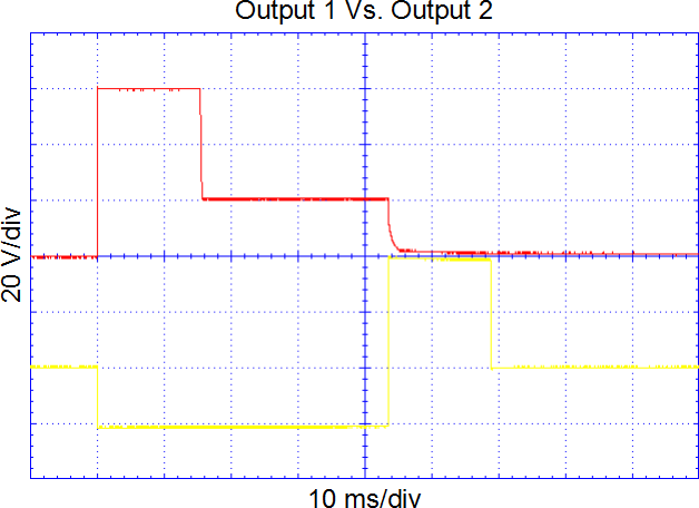
It is able to continuously power the group with a maximum of 2 A at 24 Vdc. For a faster response of the mechanical system, it controls a programmable olvervoltage up to 48 Vdc: this can be programmed via the RS232 serial port from 1 to 255 ms.
All the functions are governed by a microcontroller. In this way it is possible to implement control functions that are difficult to obtain with simple analog circuits or based on logic networks. The two channels dedicated to driving the brake and the clutch are managed independently, i.e. the timing of the overvoltage can be set with different durations.
The switching takes place by driving a suitable PNP input: if in the LOW state, for example, the brake is activated, if in the HIGH state the clutch is activated (the outputs can be exchanged, of course).
An additional input is used as an ENABLE signal: connected to the machine emergency response line, it allows to disable all outputs.
In addition to the two outputs for controlling the brake / clutch unit there are two other PNP outputs (max 50 mA @ 24 Vdc), one of which is used to indicate the so-called READY signal.
The system can also work at 12 Vdc.
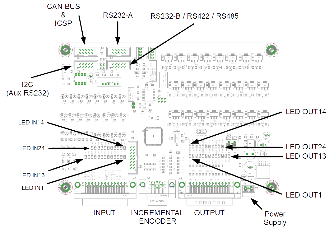
Power supply:
- one input for the voltage of 12/24 Vdc ± 10% for the control logic and brake / clutch in steady state;
- one input for the voltage of 24 ÷ 48 Vdc for the overvoltage of the brake / clutch unit.
5 PNP inputs:
- one is used as an enabling signal (READY);
- one is used to to change the state of the output (e.g. LOW = brake, HIGH = clutch);
- three more inputs are available for future uses.
4 PNP outputs:
- 24 VDC / 2 A brake power supply (up to 48 VDC) with programmable duration;
- 24 VDC / 2 A clutch power supply + supercharging (up to 48 VDC) with programmable duration;
- READY signal;
- one additional spare output manageable by the microcontroller for future applications.
RS232 serial port: (115200,8,N,1) this is mainly used to change the setup of the board, i.e. the timing of the overvoltages.
Maximum switching frequency: this is mainly overvoltage time dependant.
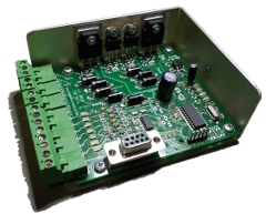
Dimensions: 9,8 cm x 8,8 cm
For more information, please use the following form.