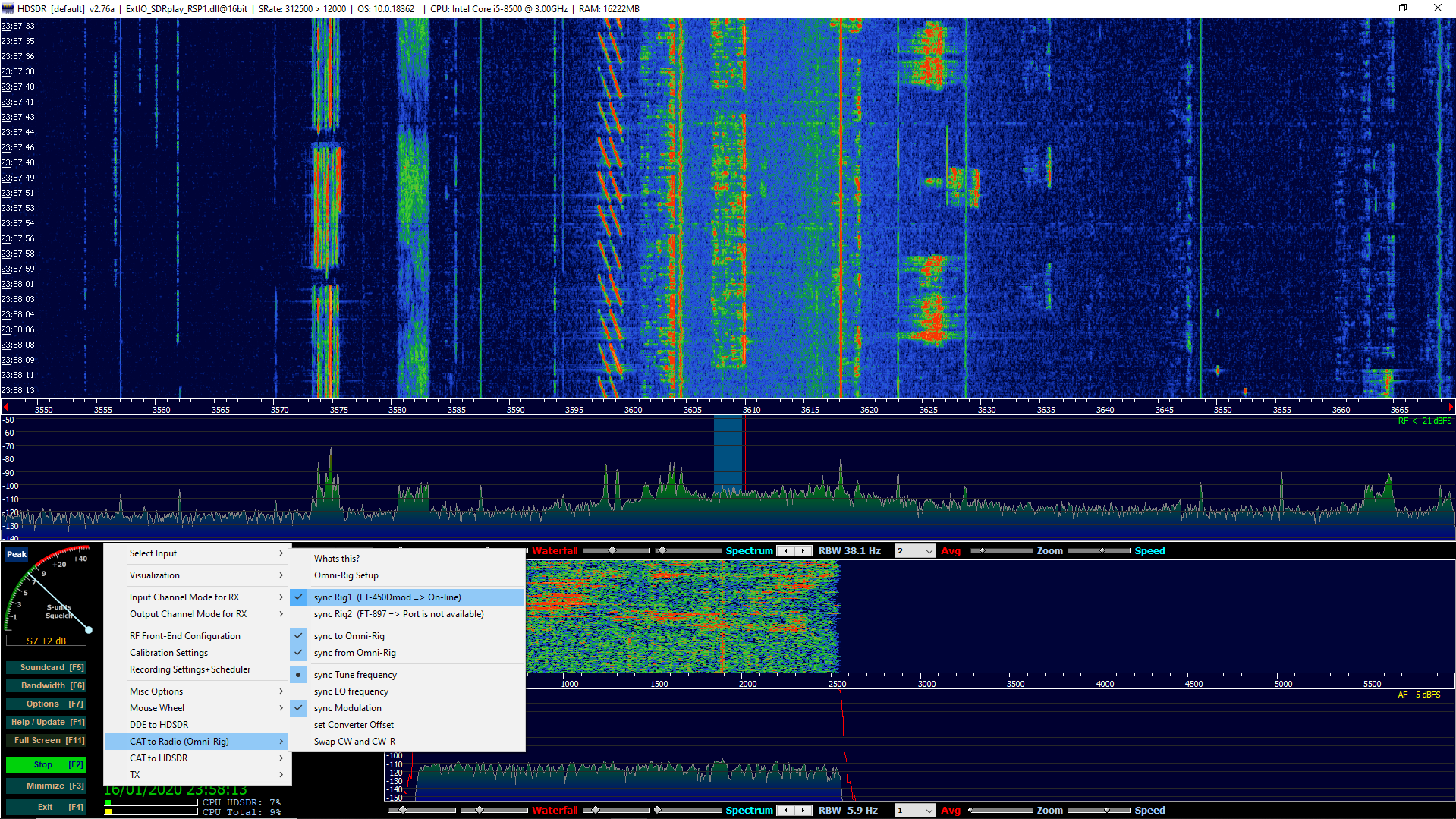
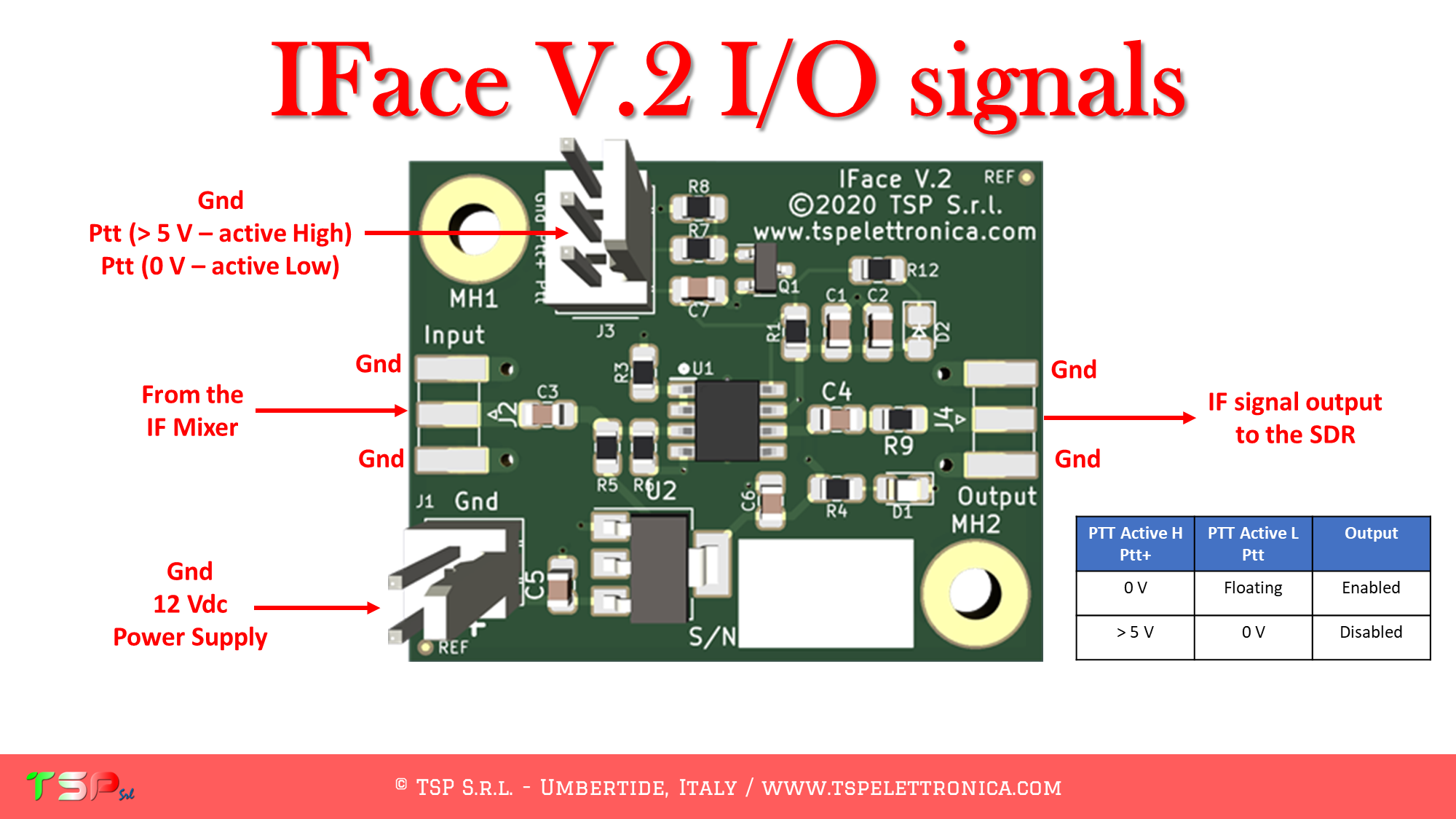
Our buffer interface named IFace can be used to add an SDR panadapter to the YAESU FT-991A.
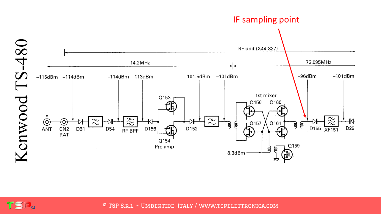
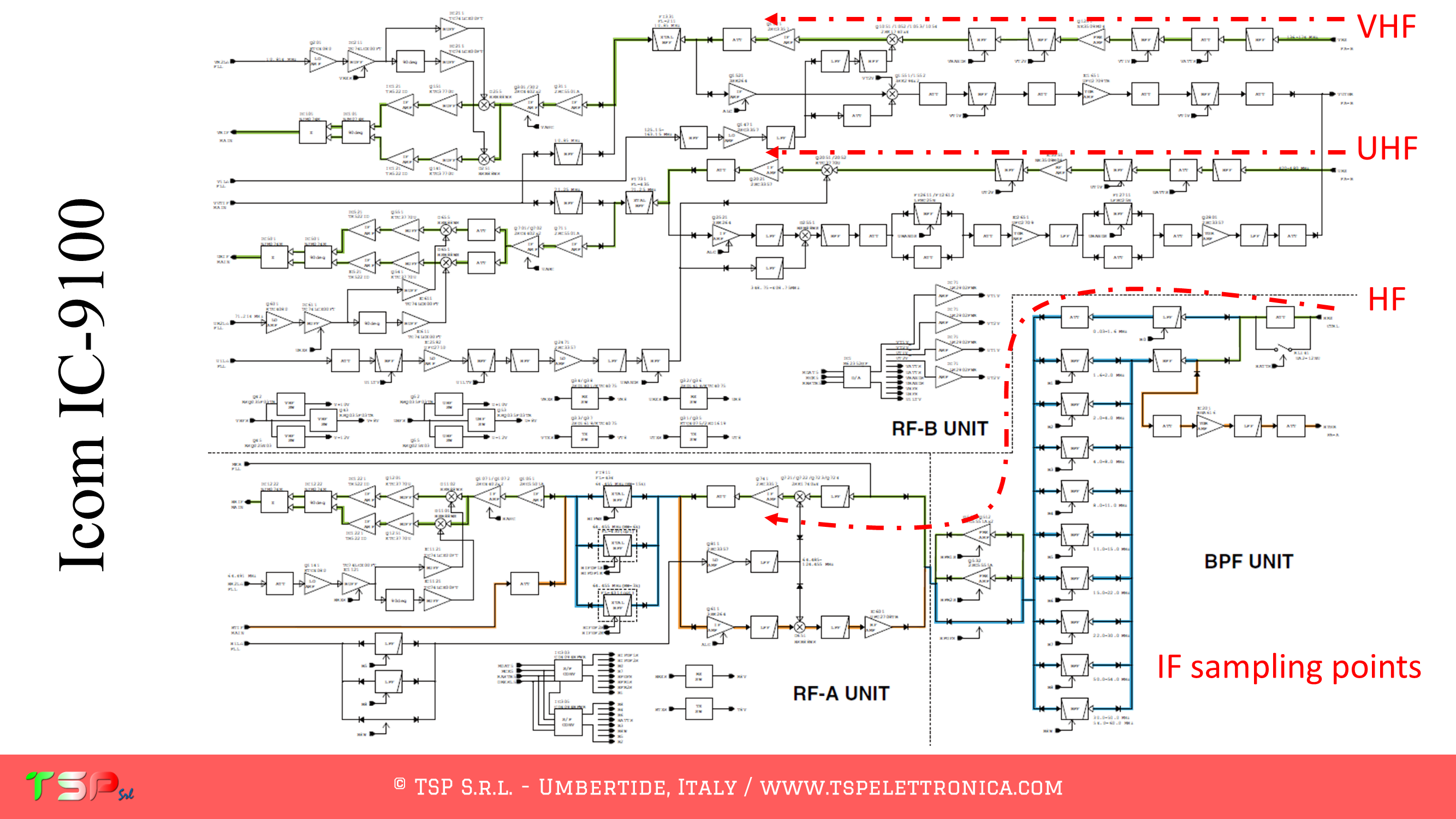
The operations to be performed are very simple, it is sufficient to obtain from its wiring diagram the information on the points where to take the IF signals. This radio, in fact, uses different mixers. In particular, we will have to use the first of the RX chain. The following imagea show the block diagram of the radio. For the FT-991A the first IF is at 69.450 MHz.

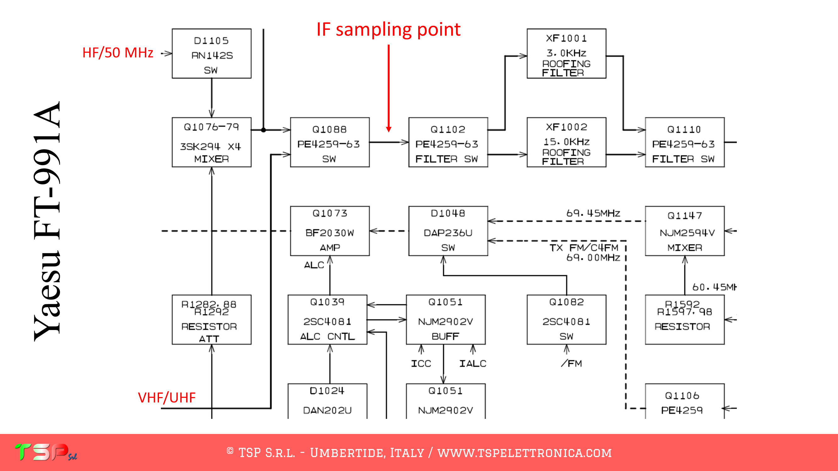
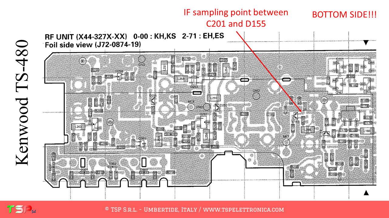
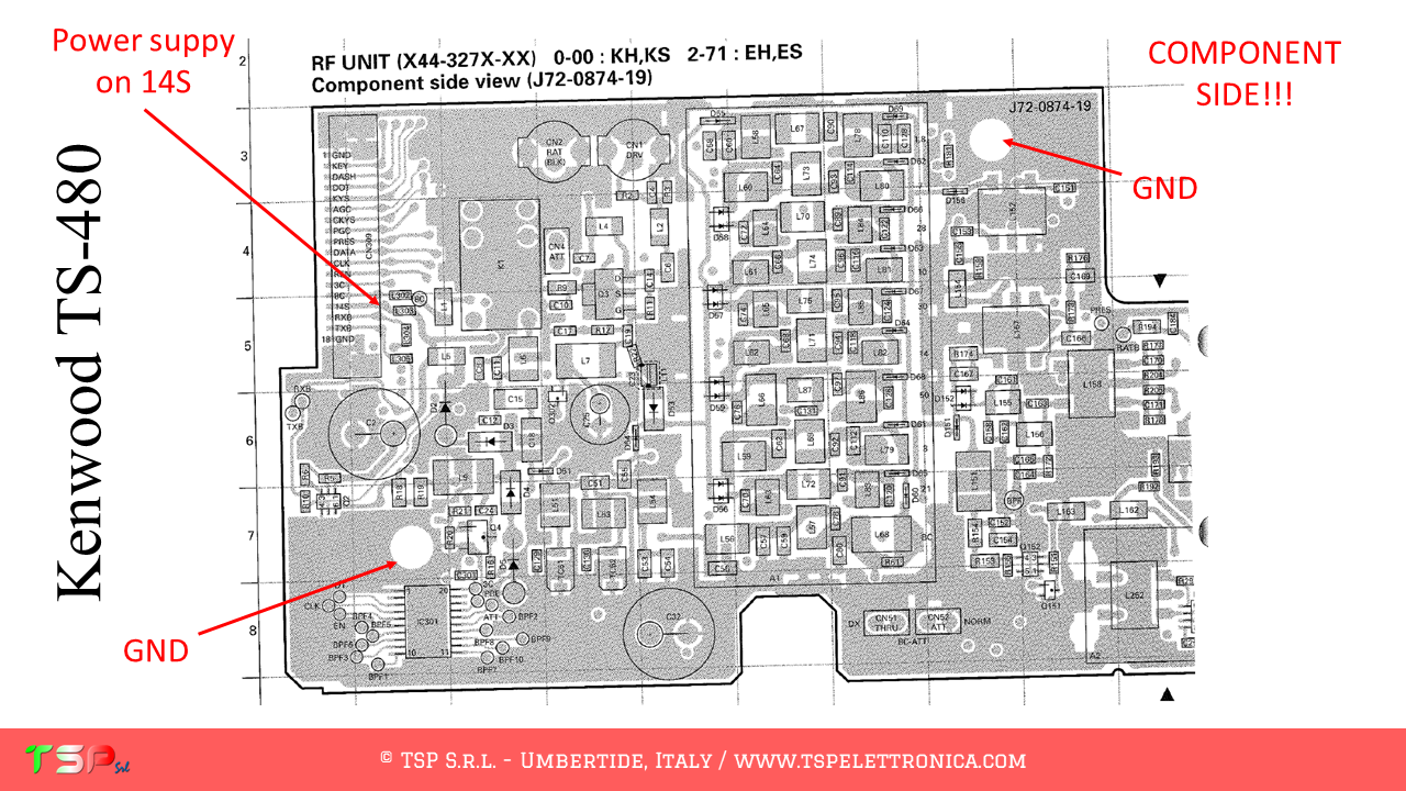
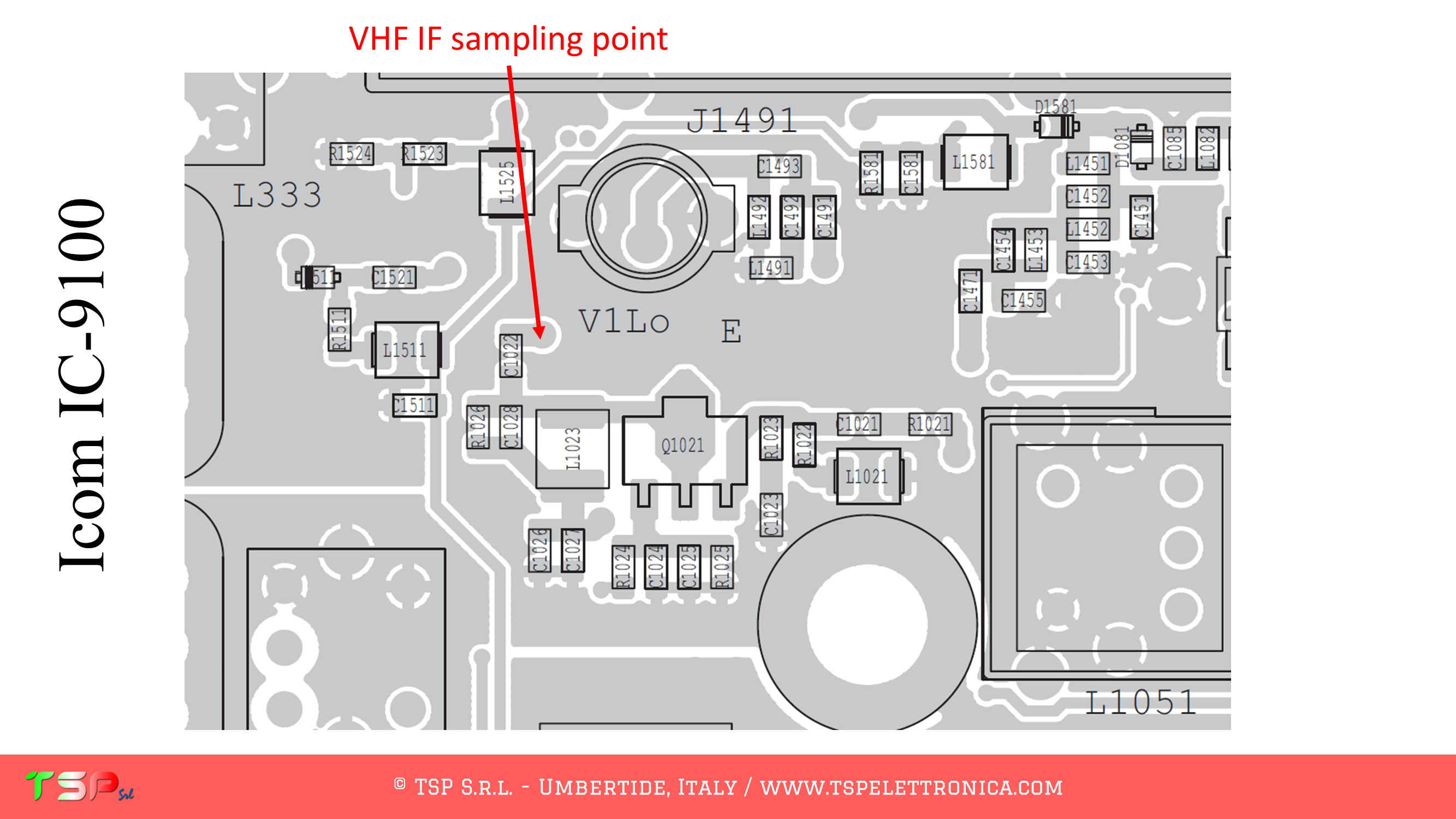
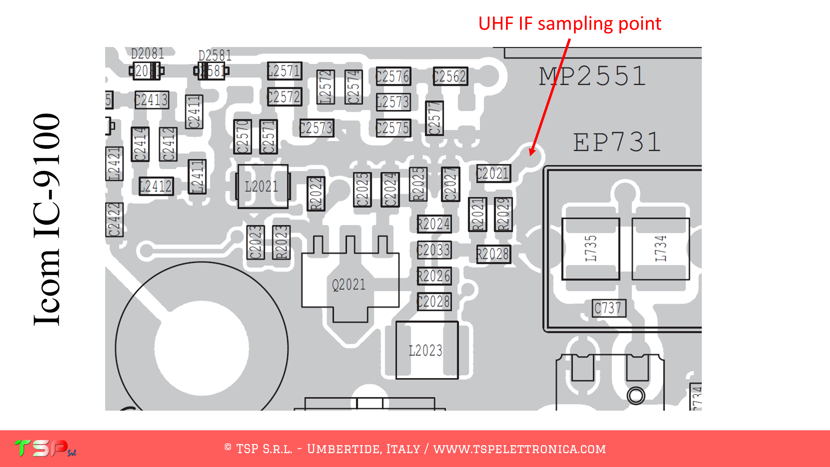
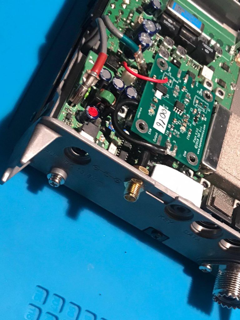
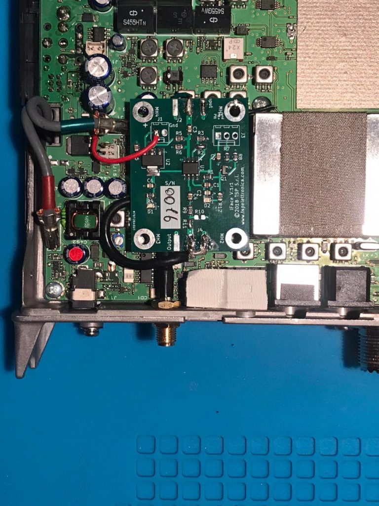
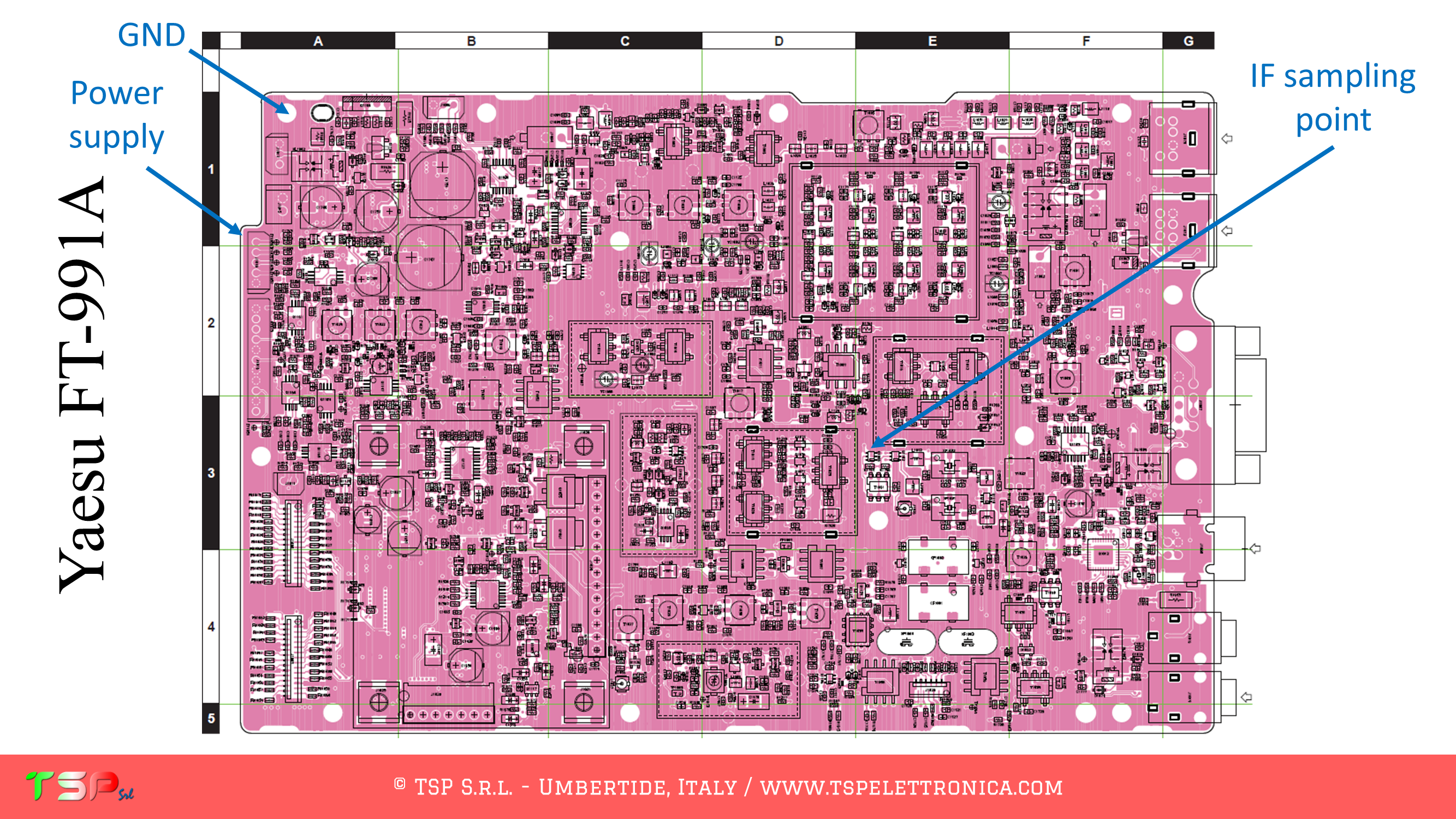
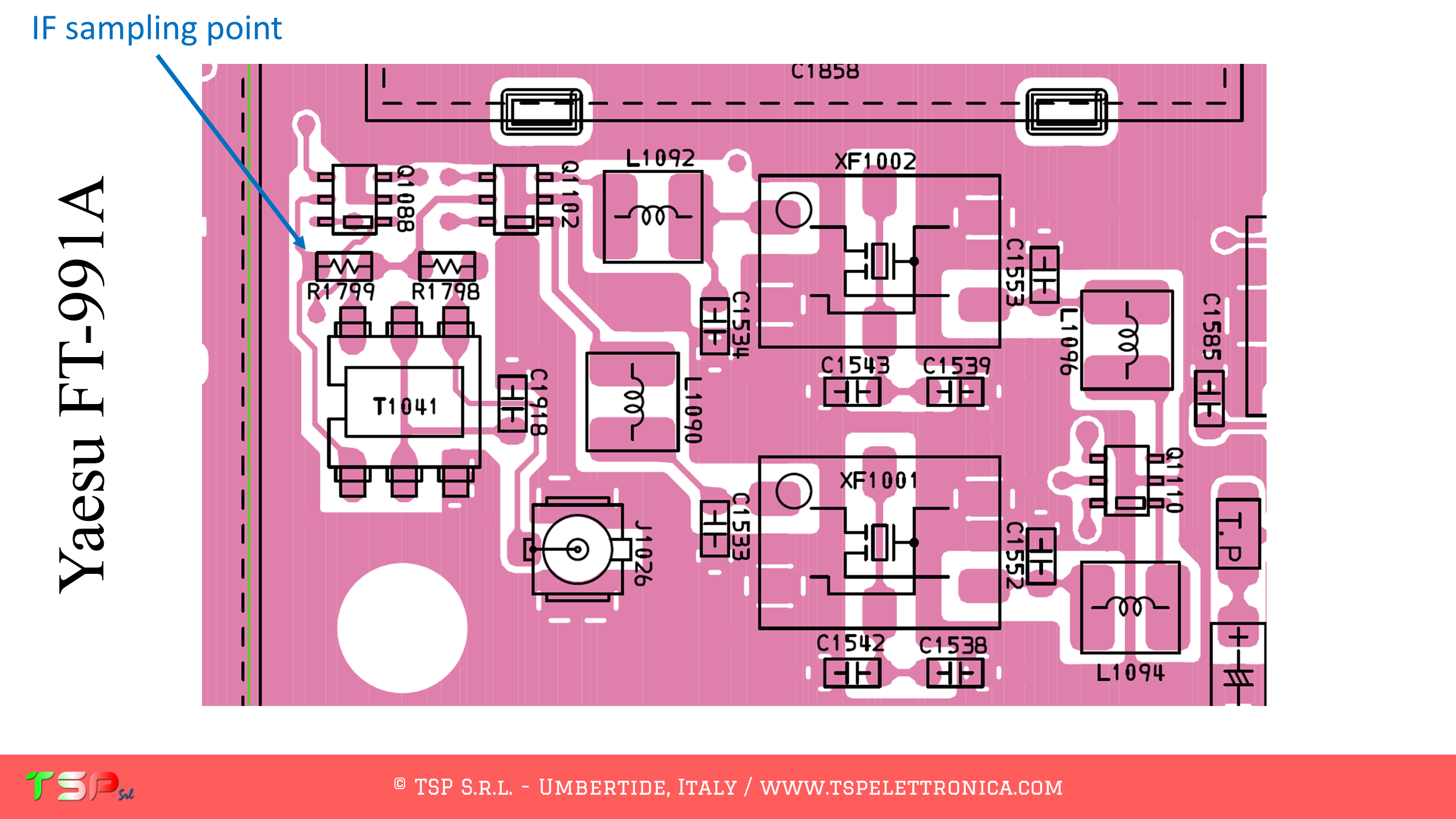
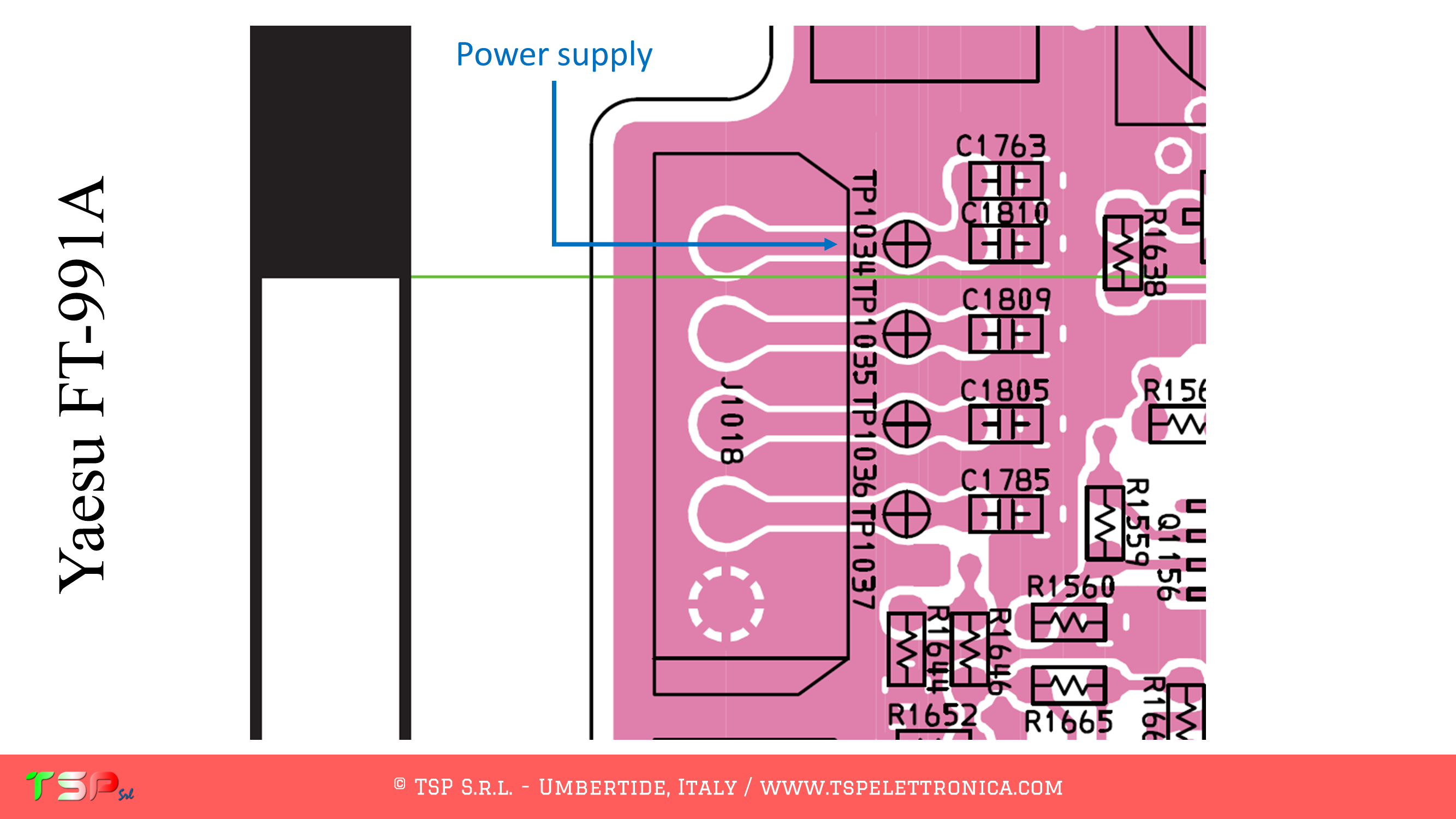
We now proceed to identify the exact points on the circuit diagram where to take the IF signal to be sent to the IFace. The following images show the sampling point for the IF signal and for the power supply for the buffer interface.


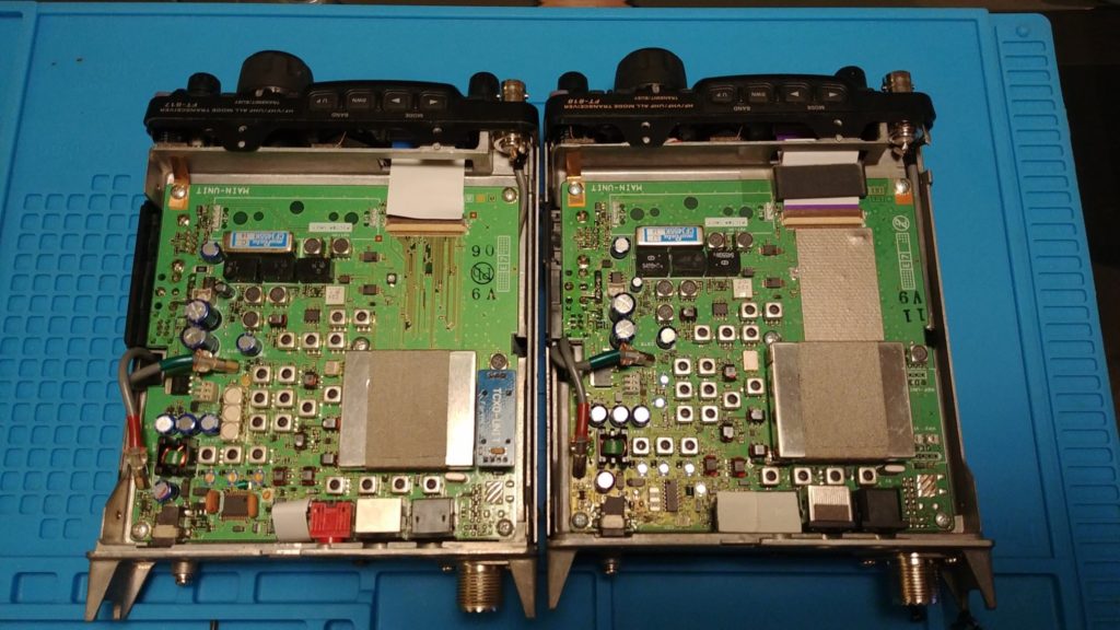
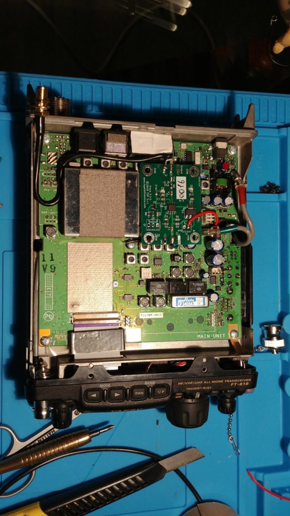
The images here below show where the signals are located on the MAIN UNIT PCB. Please take care that the signals are located on the top and on the bottom layer.
The PTT signal is not required.
In order to purchase an IFace use the button below.

ATTENTION: Though installing the IFace is not difficult, you do this at your own risk. TSP S.r.l. is not responsible for any damage, unwanted side-effects or whatever.
For more information, do not hesitate to write to us using the form below.
Have fun!