Follow the steps below to install the IFace card in the YAESU FT-897. Installation is really very easy.
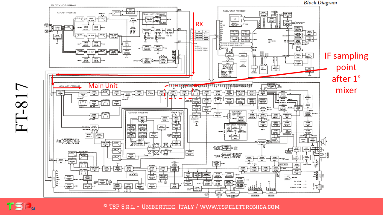
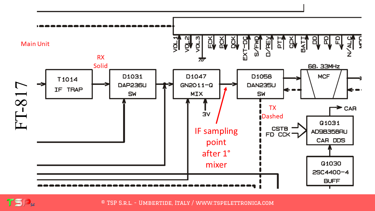
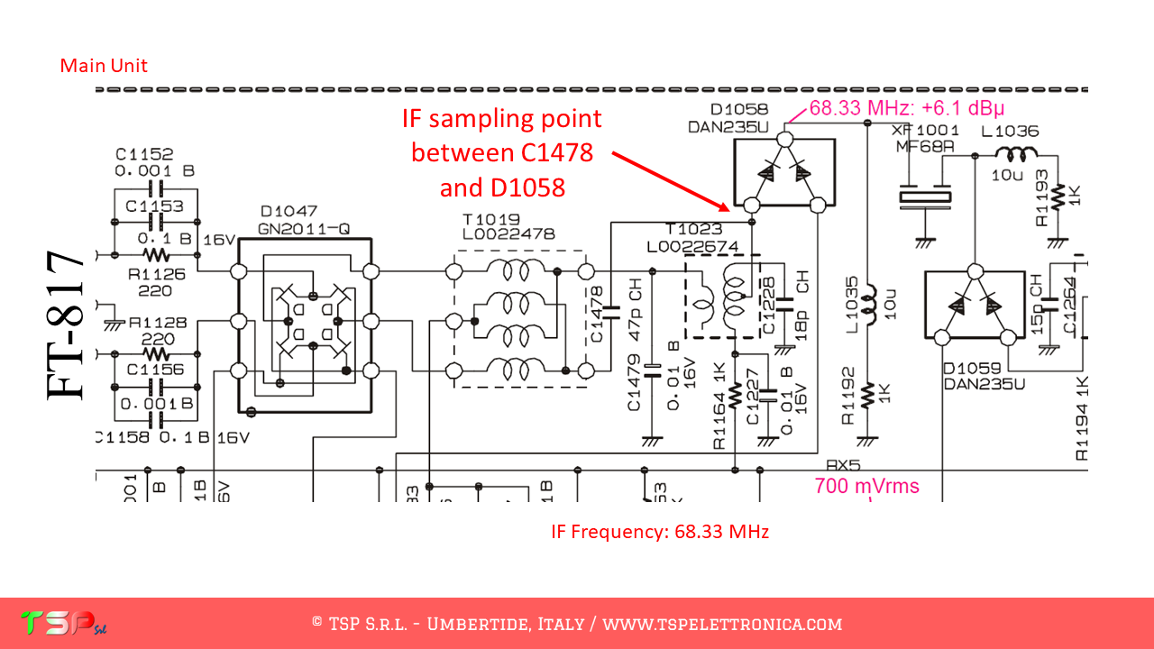
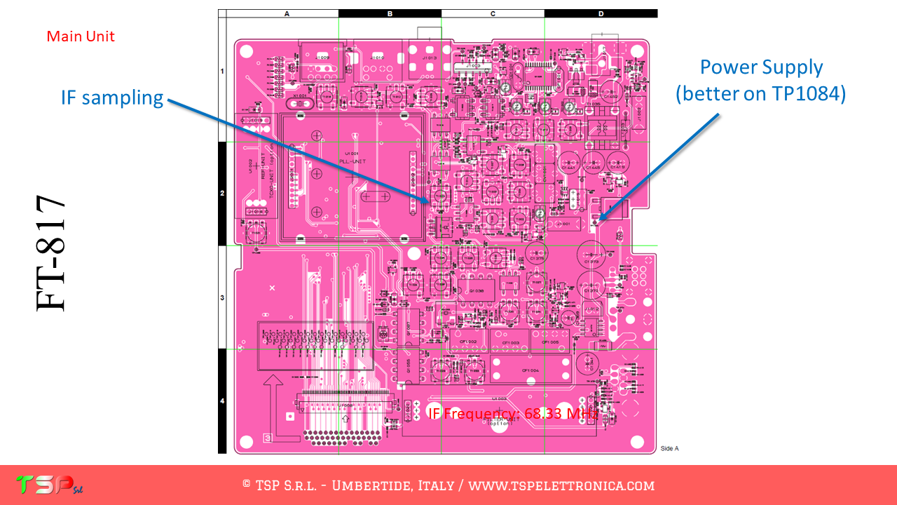
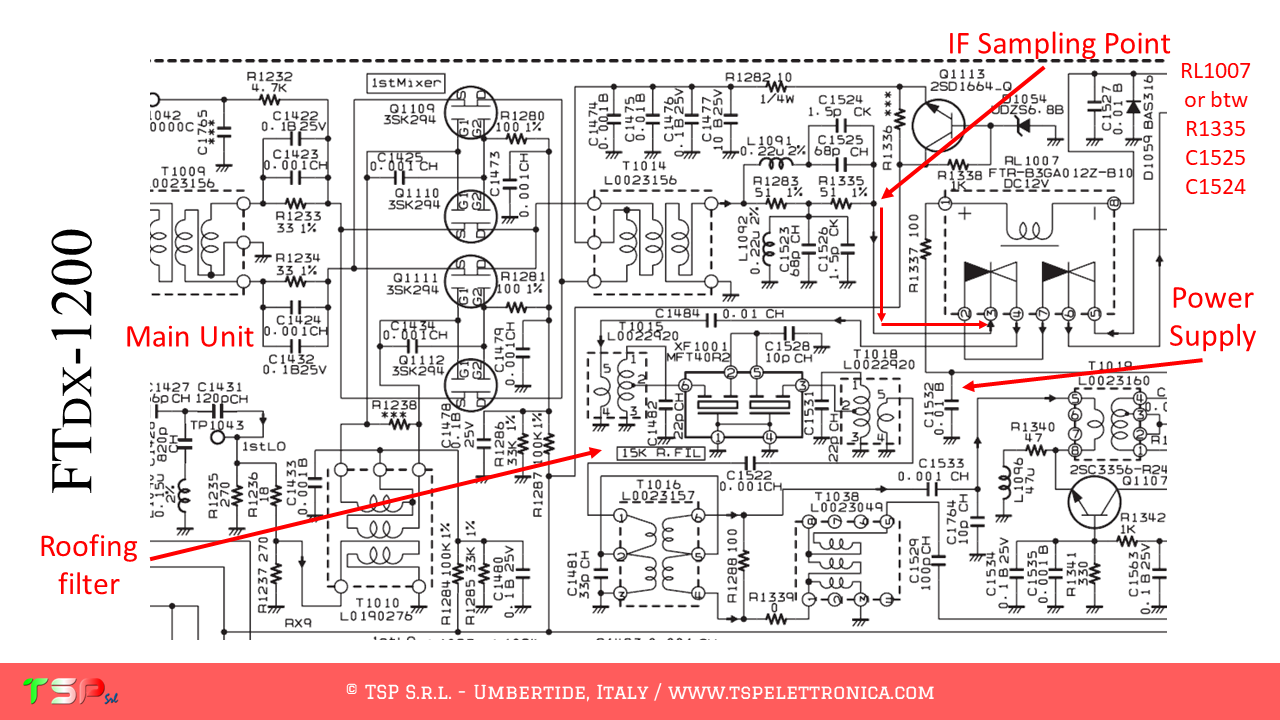
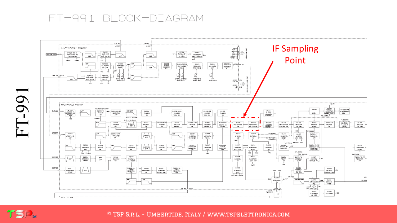
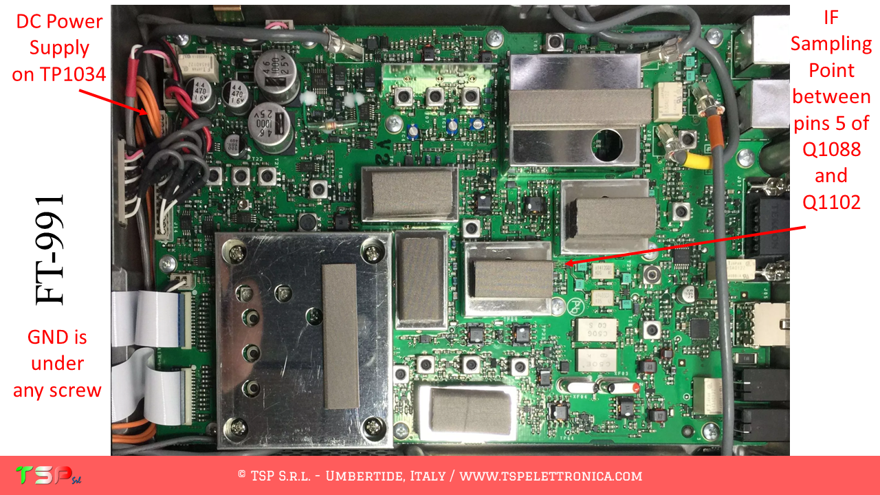
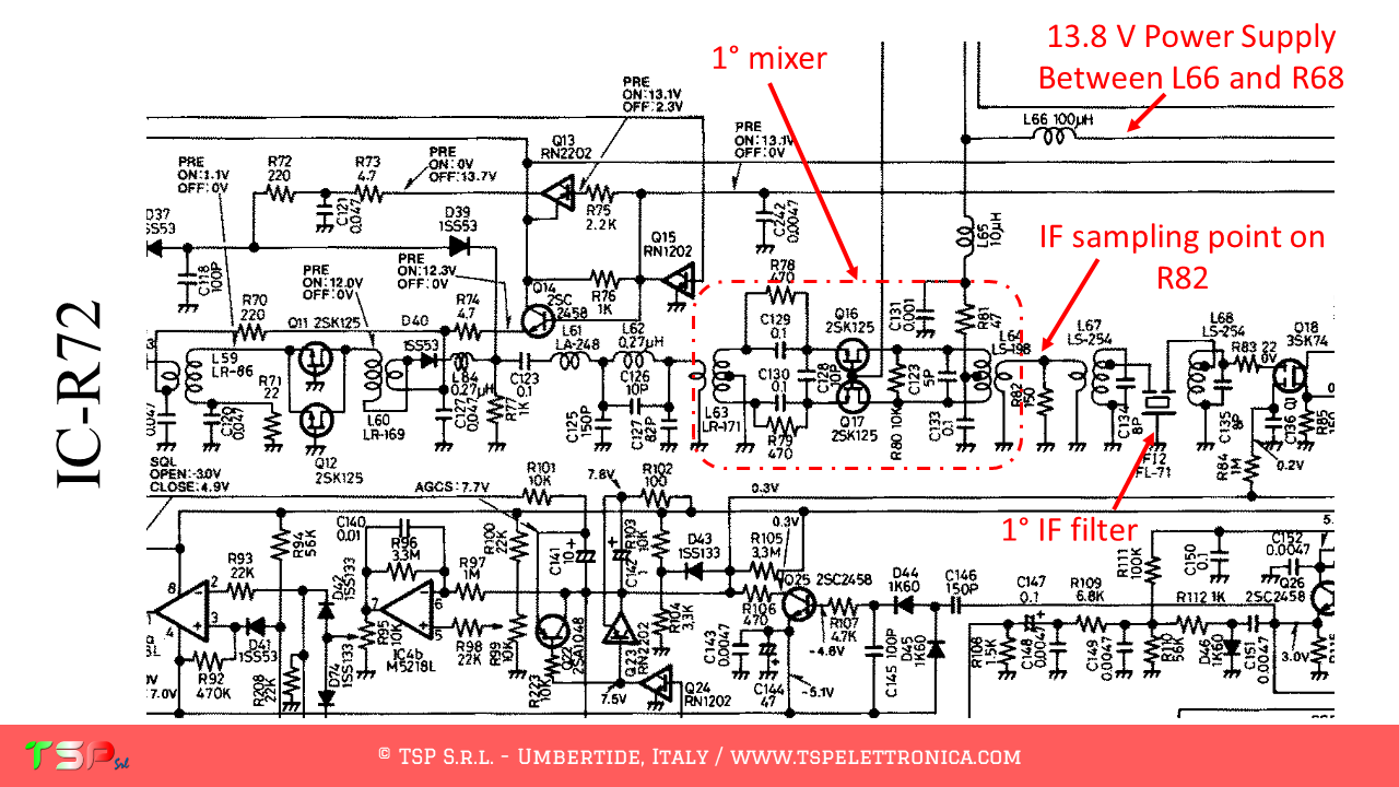
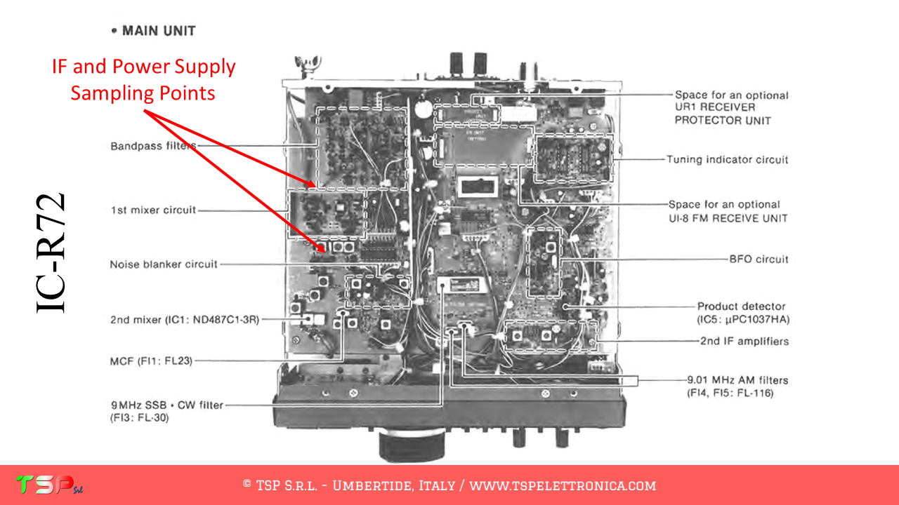
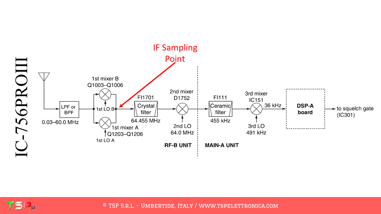
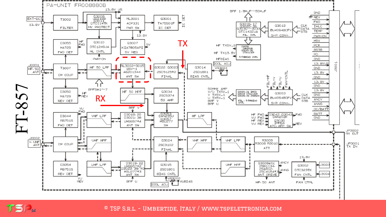
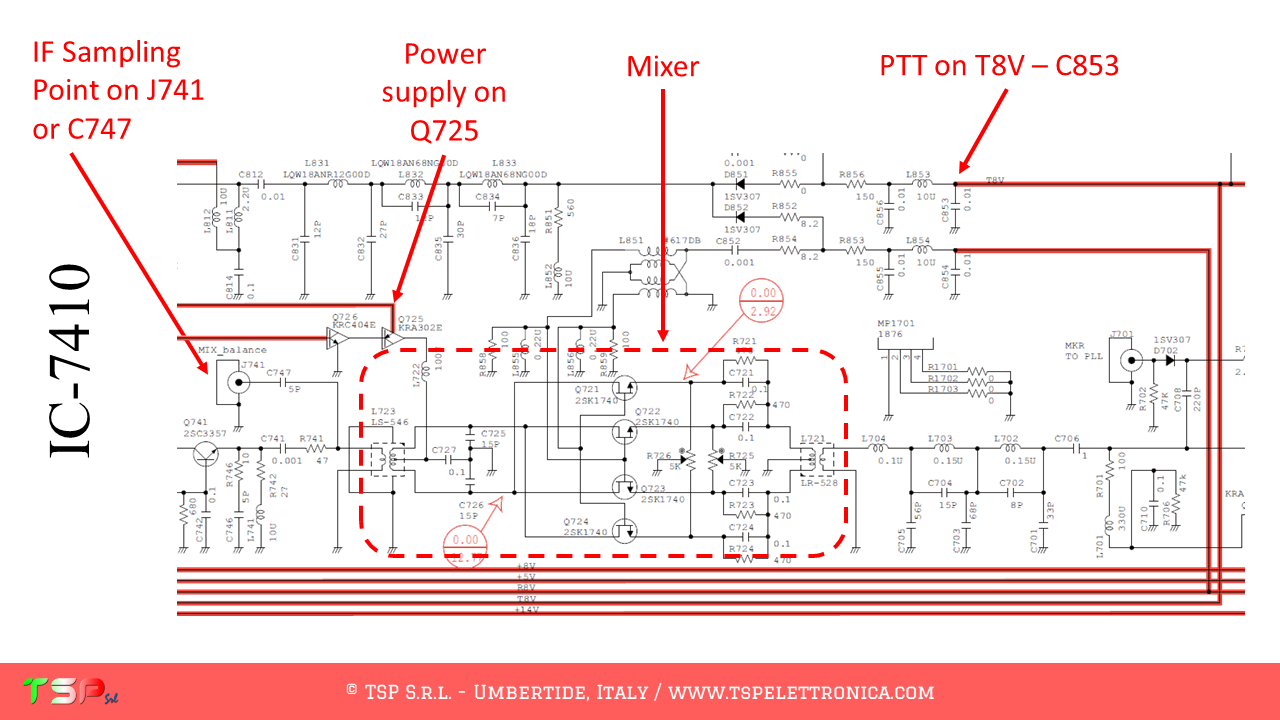
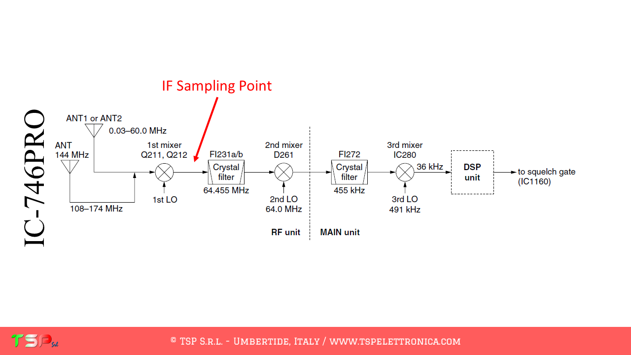
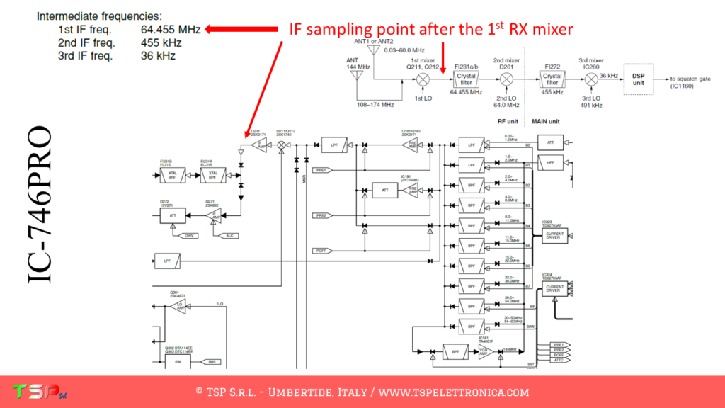
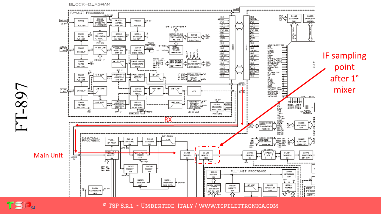
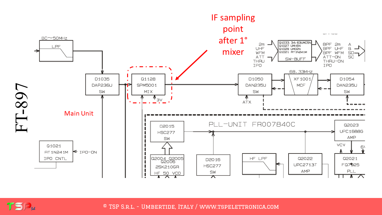
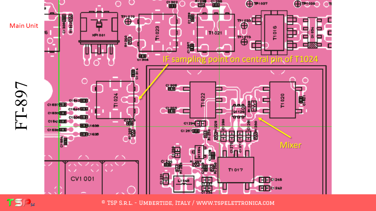
As always we start from the block diagram and try to find information on where to get the first intermediate frequency signal. We use the first because it is not filtered, i.e. the band is still wide. The following images make it very clear where this point is located. The PTT may not be necessary, the TX and RX circuits are well separated.
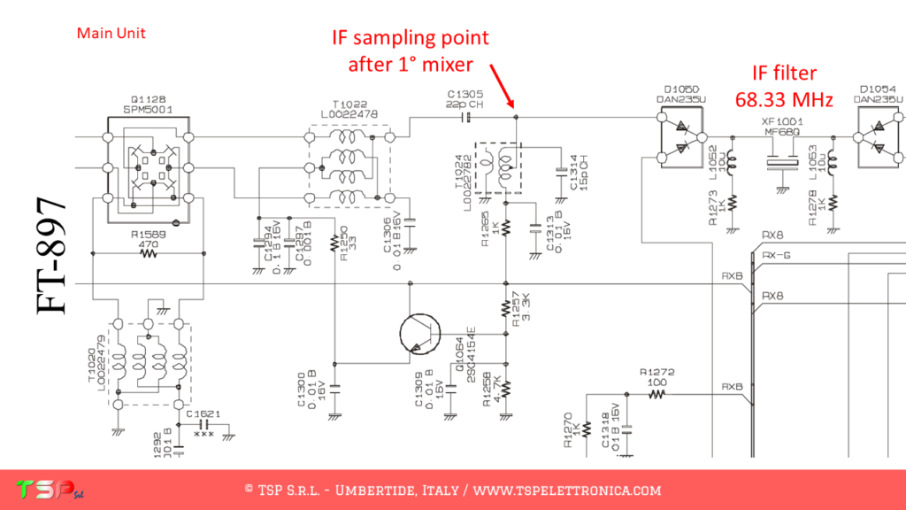
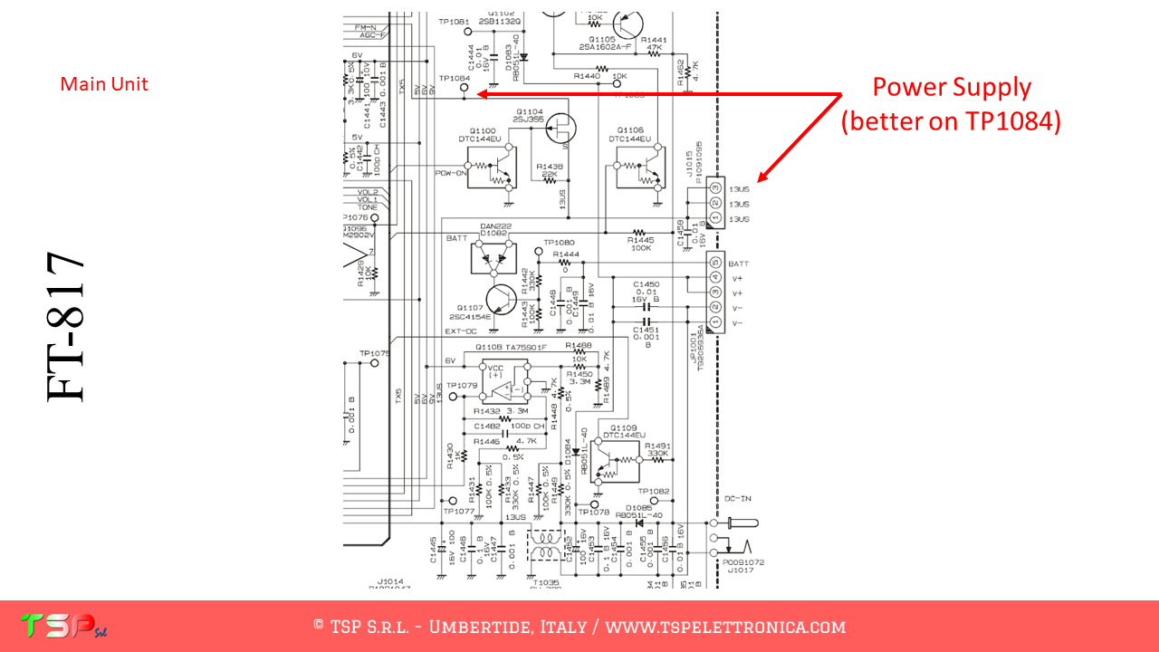
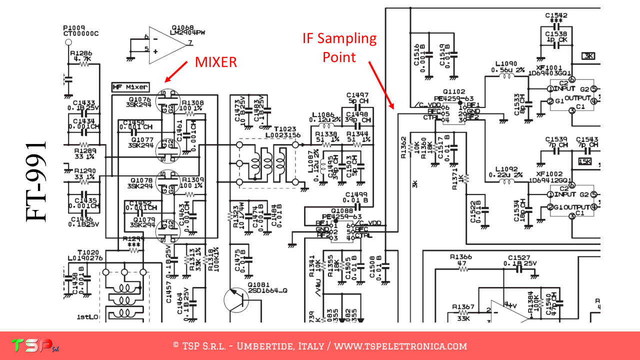
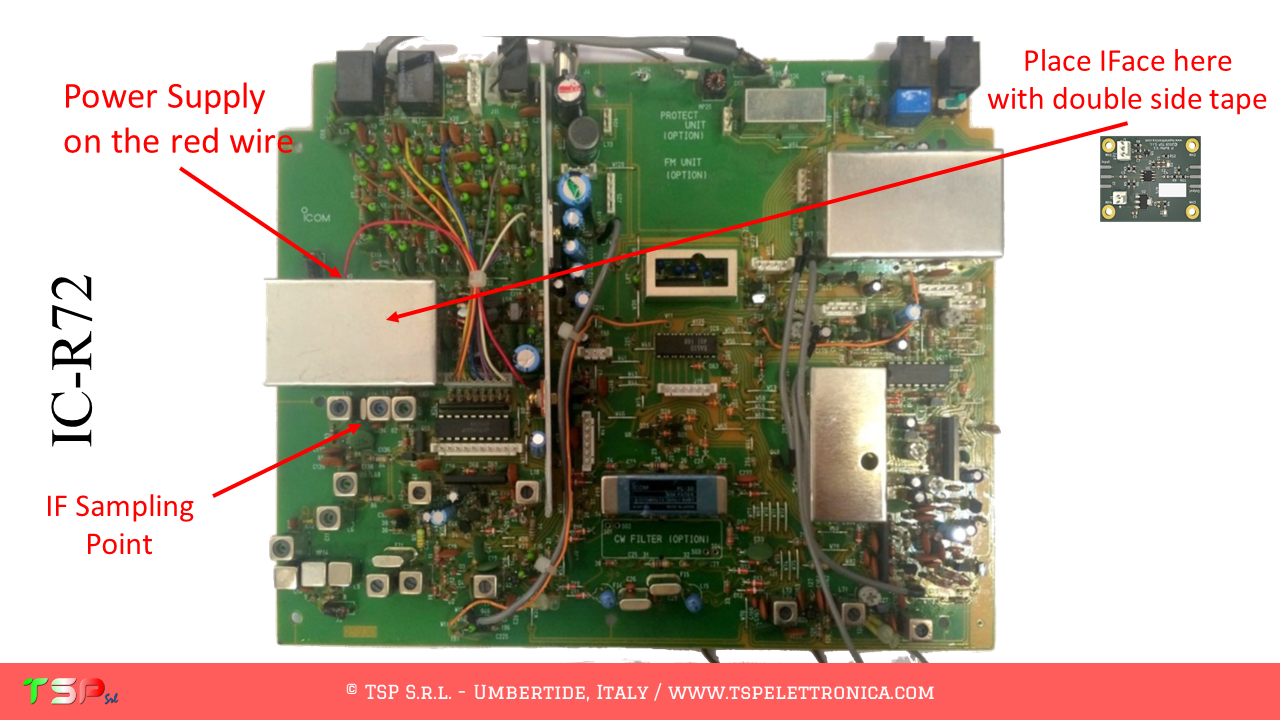
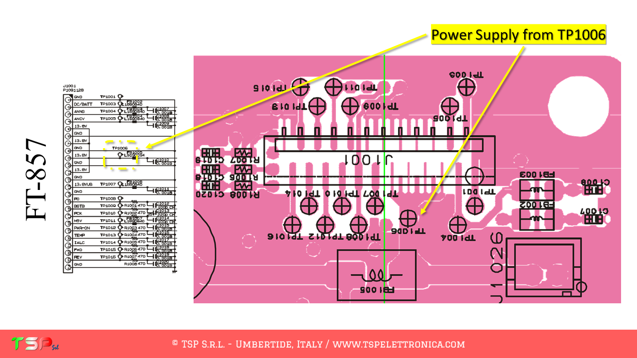
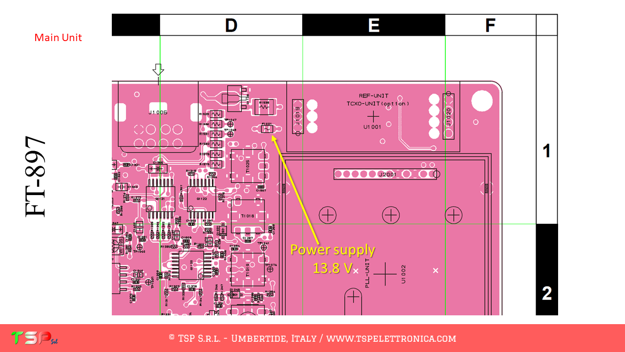
The power supply can be taken soldering a thin wire on the fuse F1001.

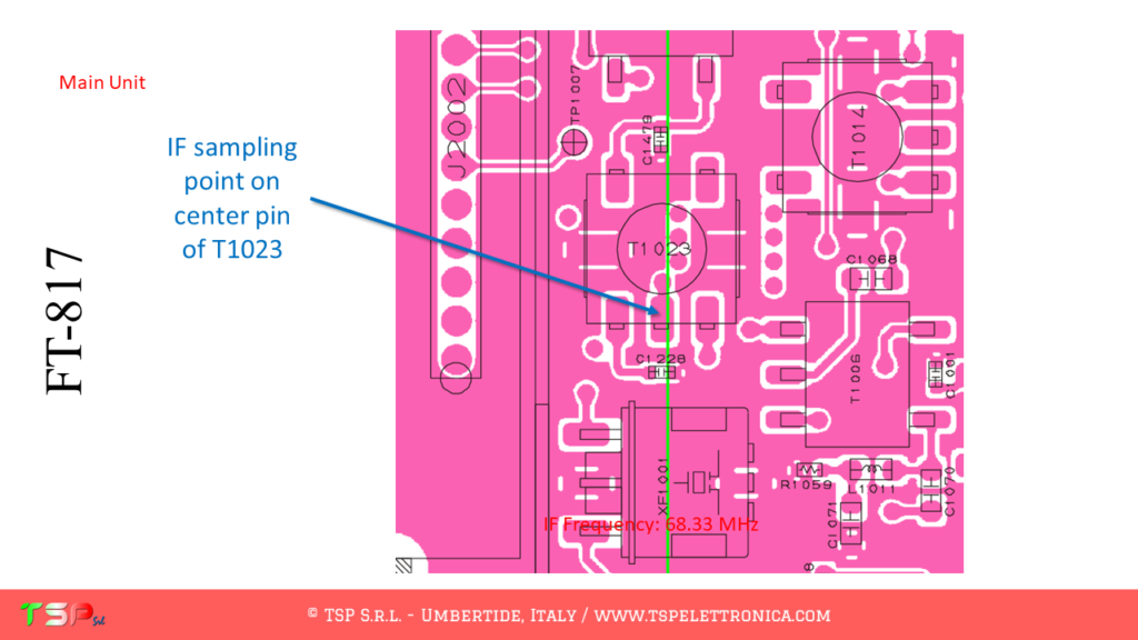
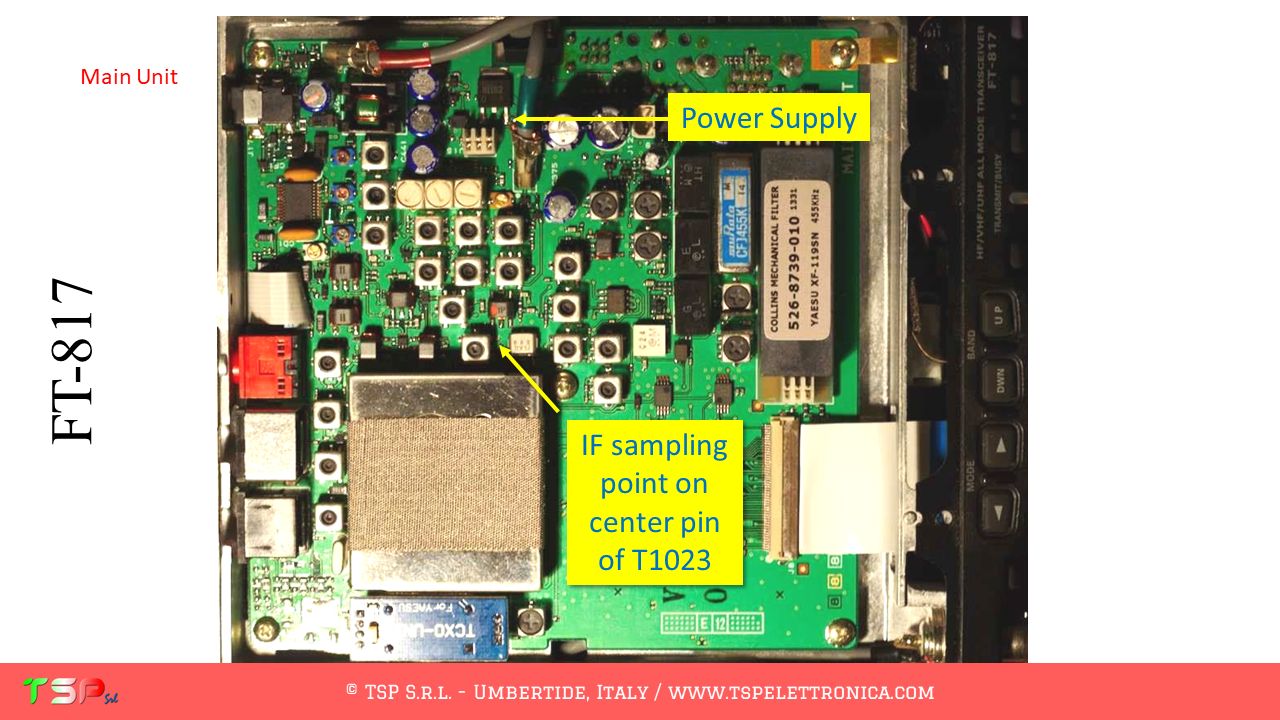
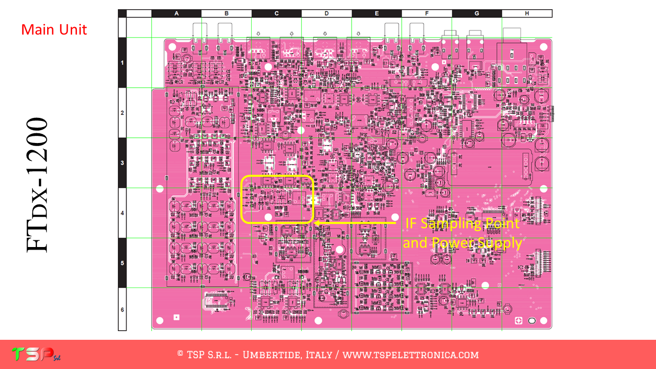
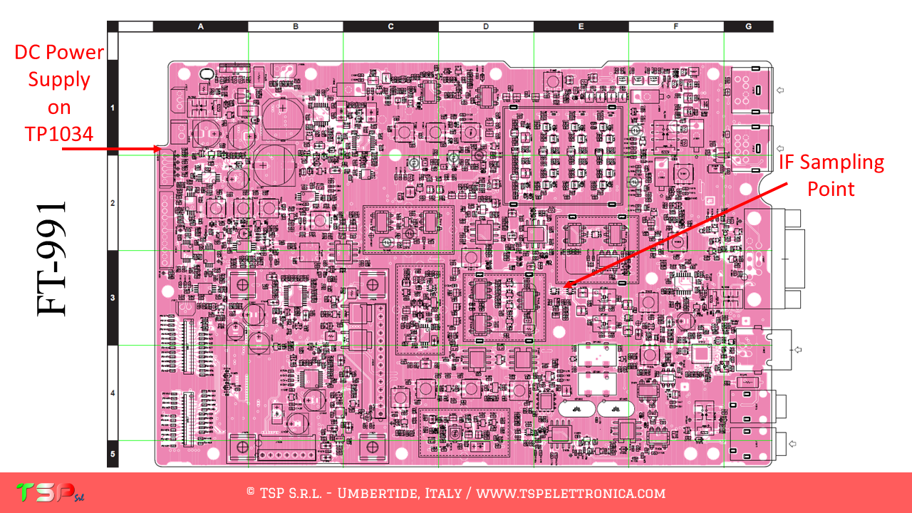
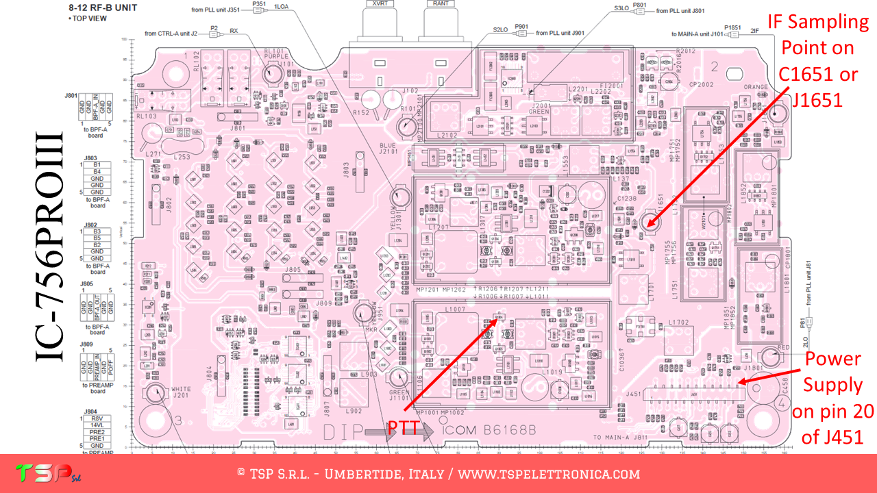
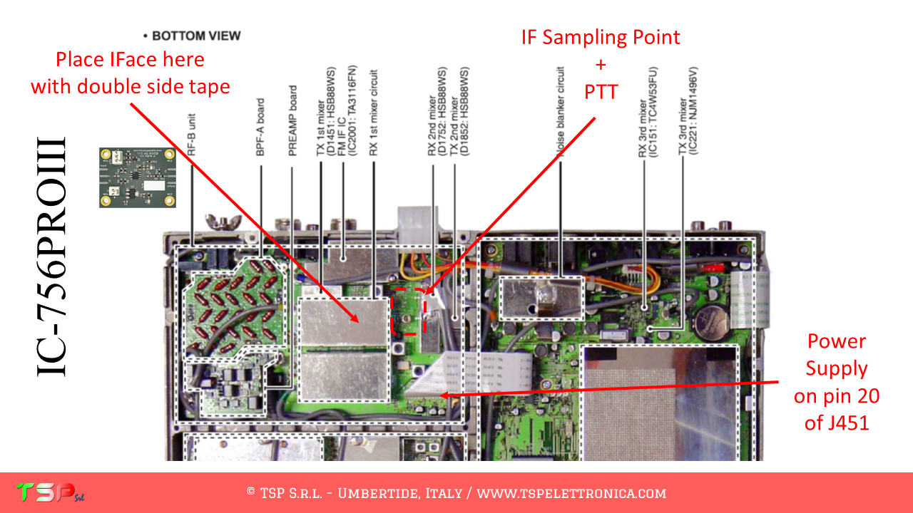
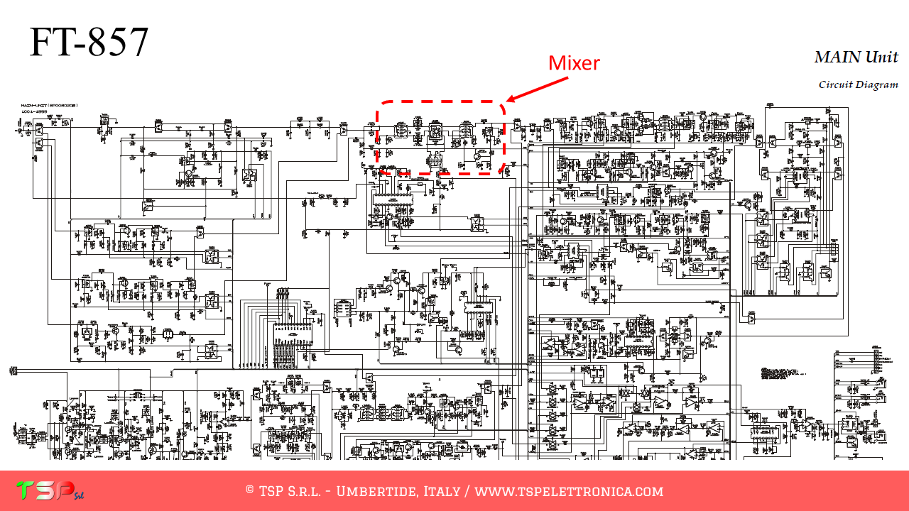
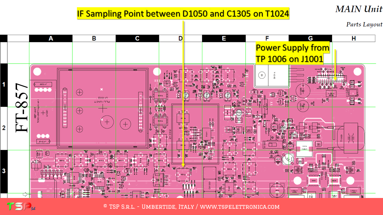
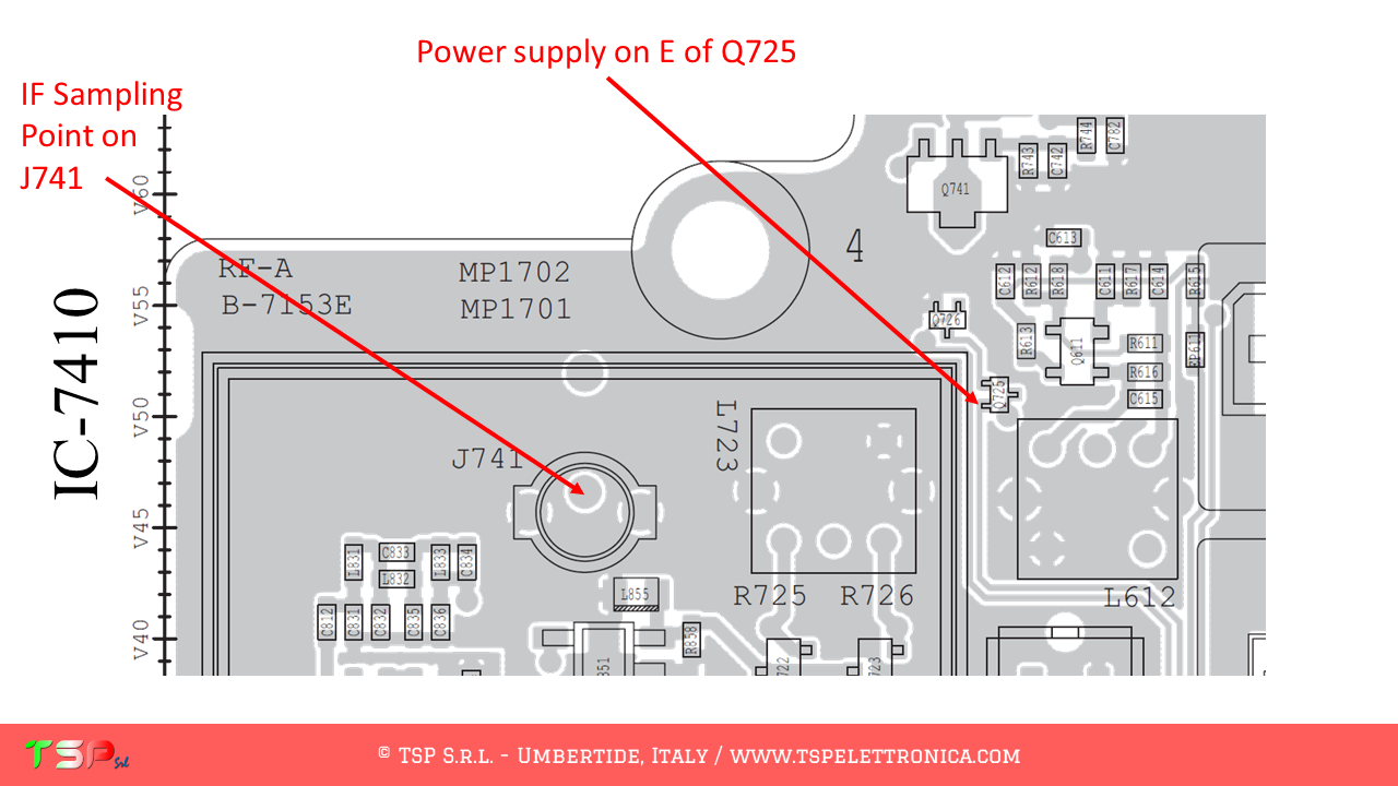
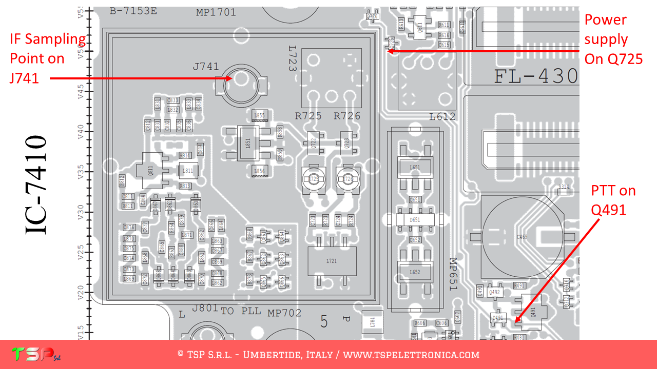
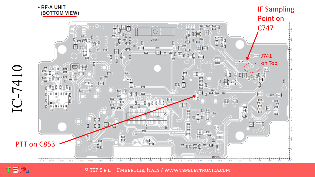
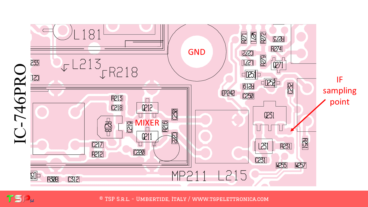
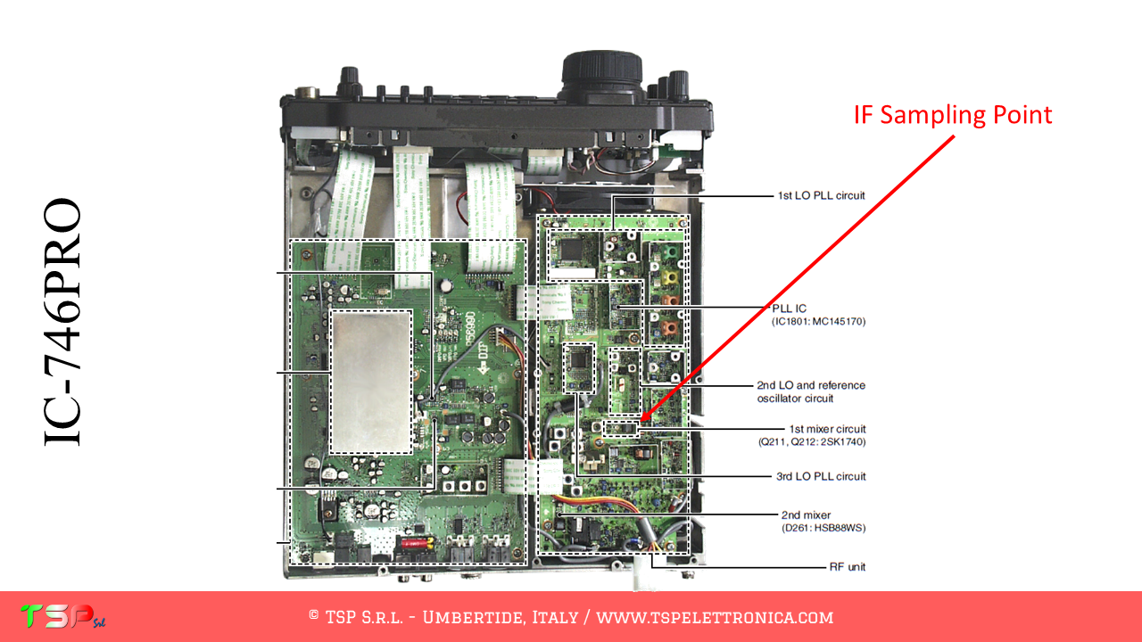
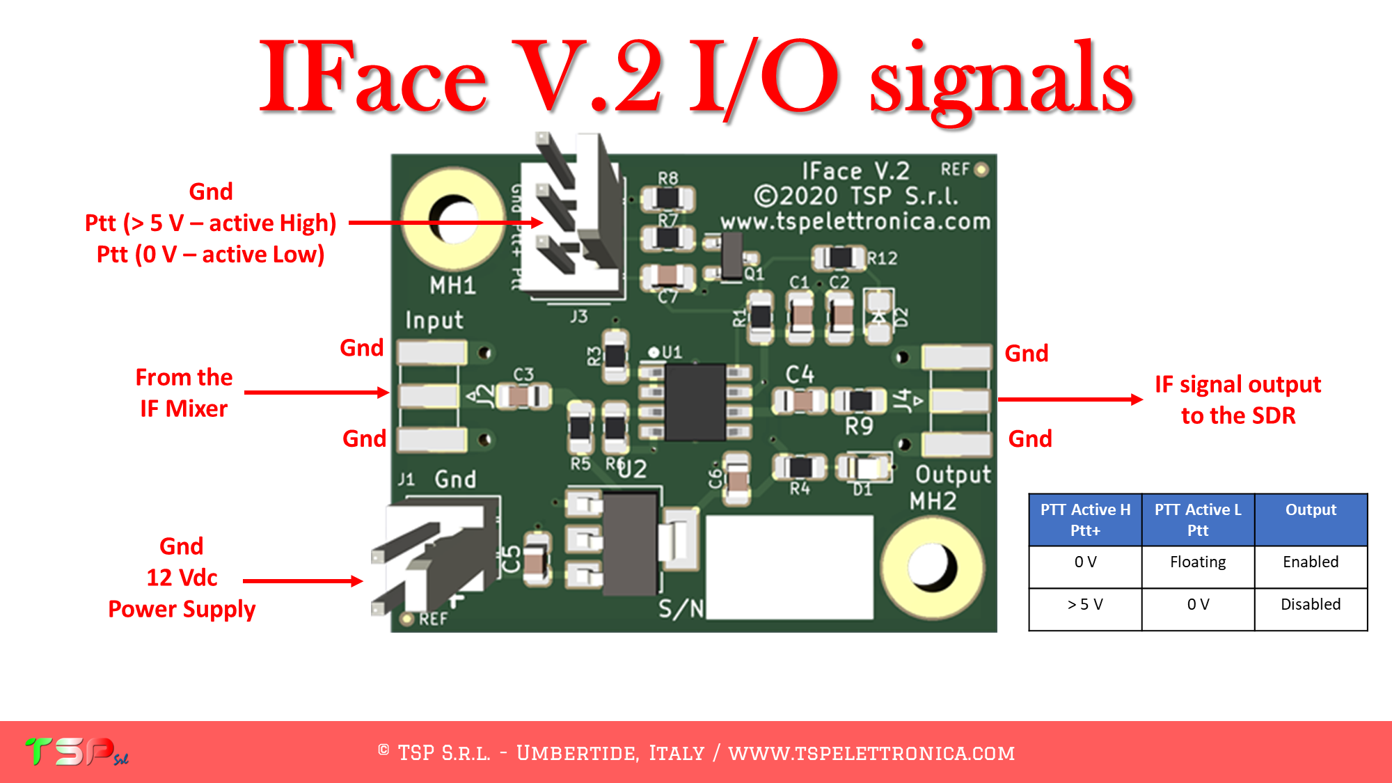
At this point all that remains is to identify the points on the PCB where to take the signals: refer to the following images.


If you are convinced of the goodness of the proposal buy an IFace using the button below.

WARNING: Although the installation of IFace is not difficult, it is done at your own risk. TSP S.r.l. is not responsible for any damage, unwanted side effects or anything else.
For more information do not exist to write to us.
Have fun!