December 26, 2020

SDR interface for the IC-756PRO

These are the instructions to install the IFace interface inside of the Icom IC-756PRO. The installation is very easy.

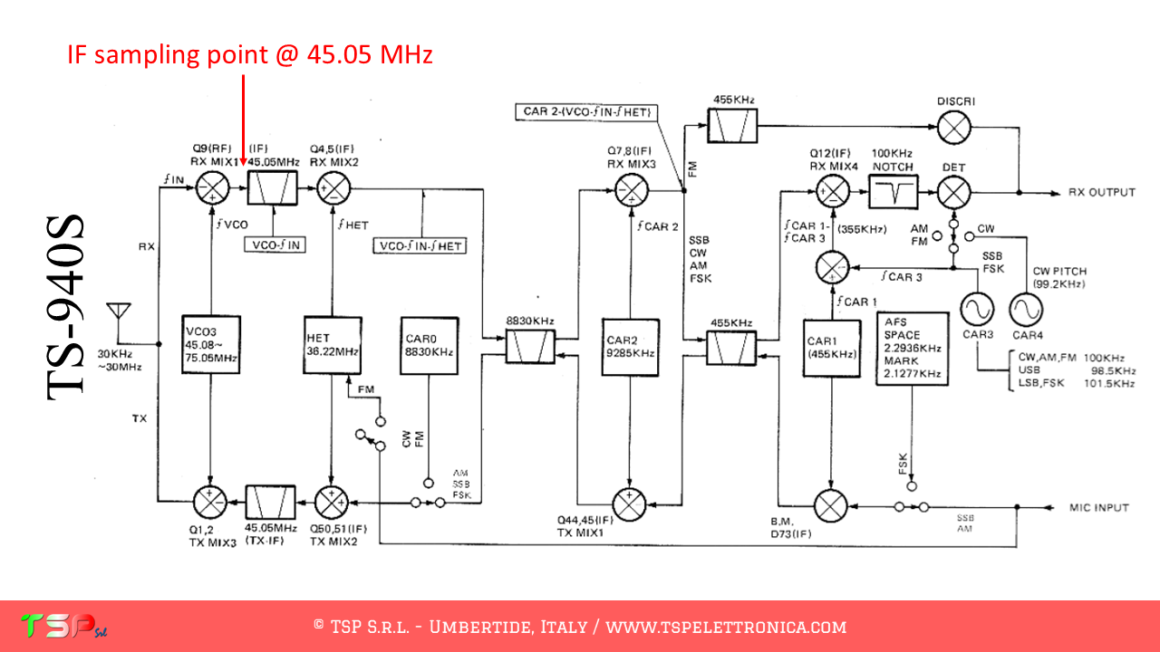
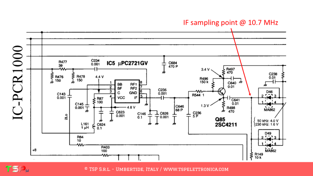
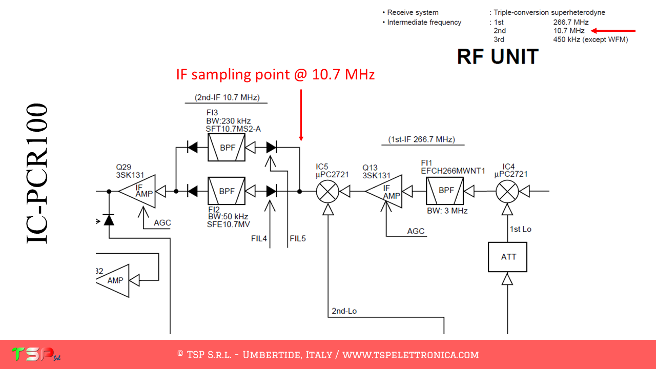
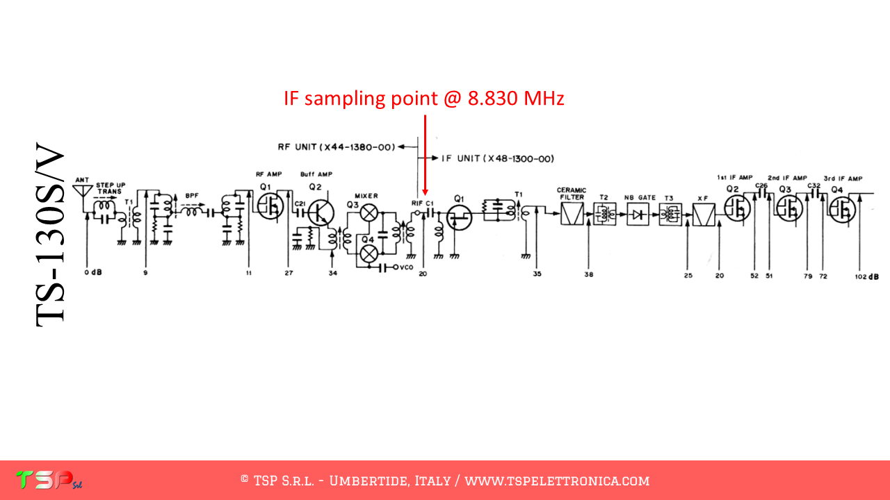
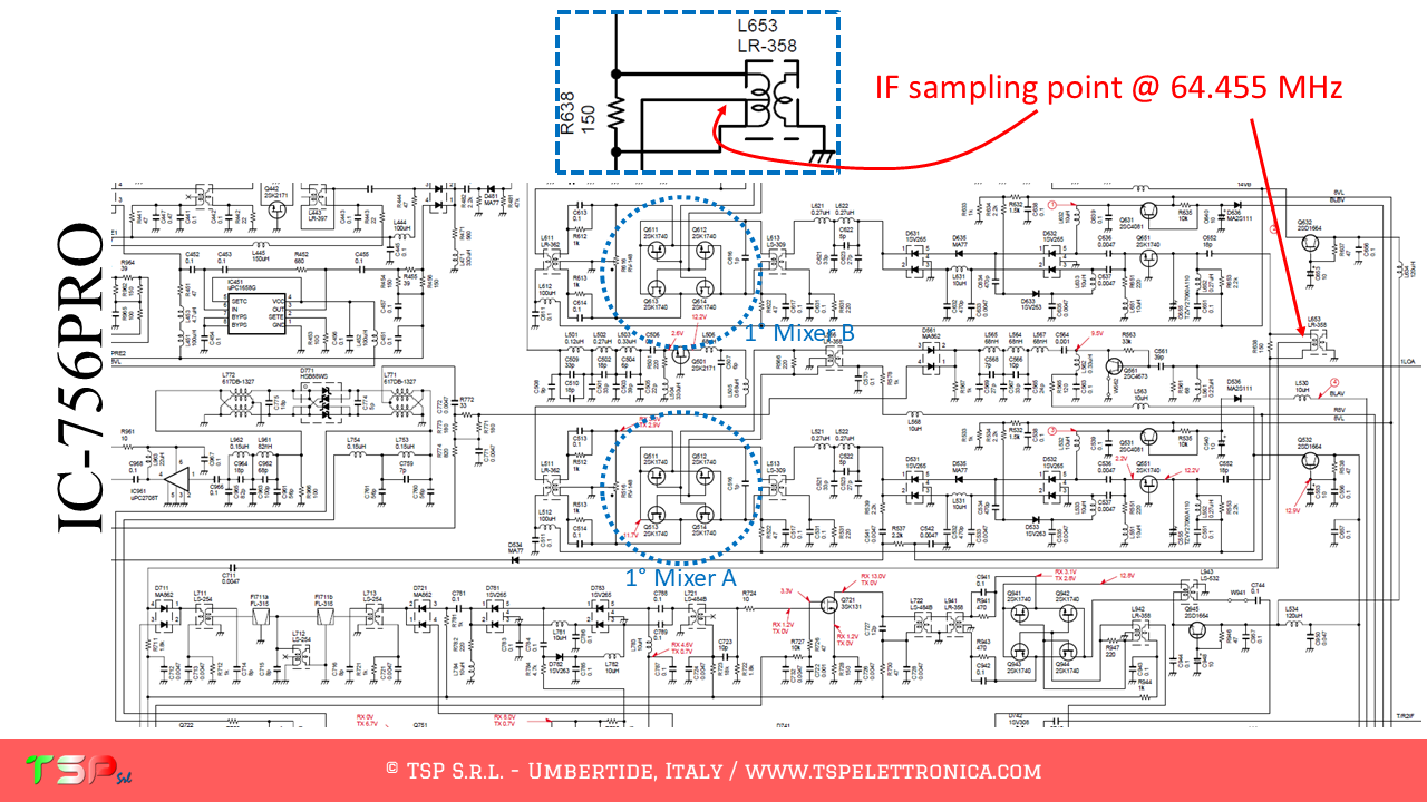
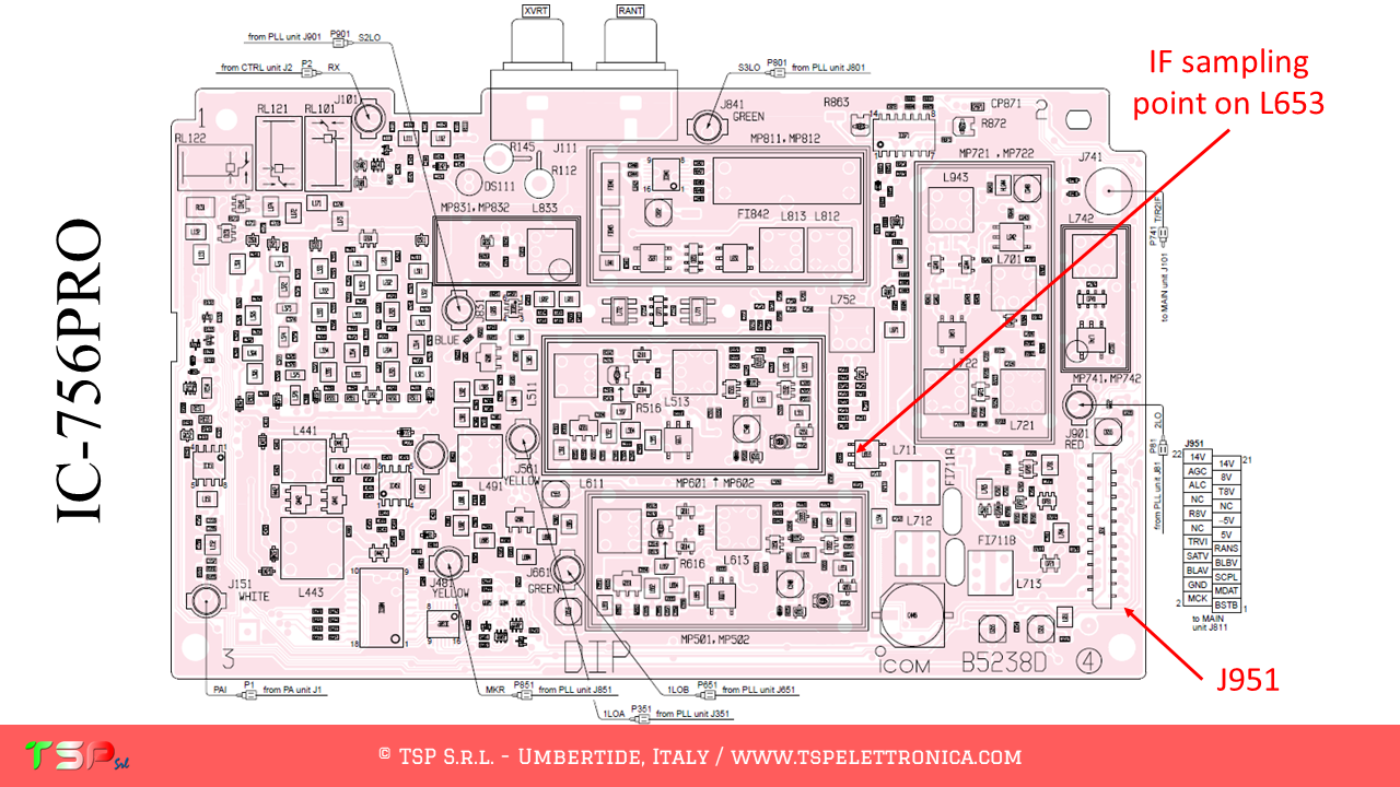
The IC-756PRO, as well as other radios, has a fairly complex configuration and uses three different intermediate frequencies. We are interested in the first, the “wideband” one, the first one before the main bandpass filter (the 15 kHz roofing filter). Below you can find some images that illustrate how to install the interface for SDR. The following image shows the point where the IF signal will be taken. The first IF frequency is 64.455 MHz.

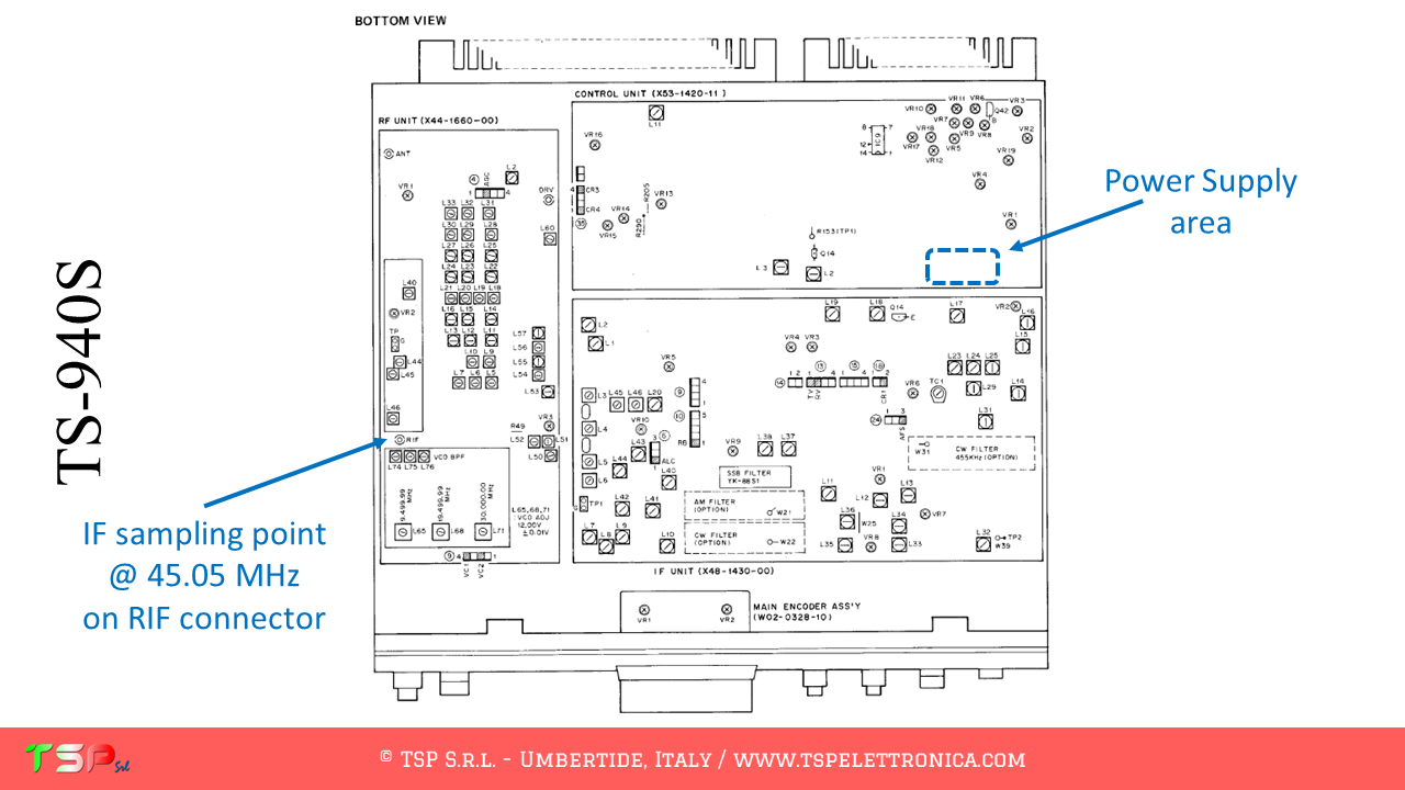
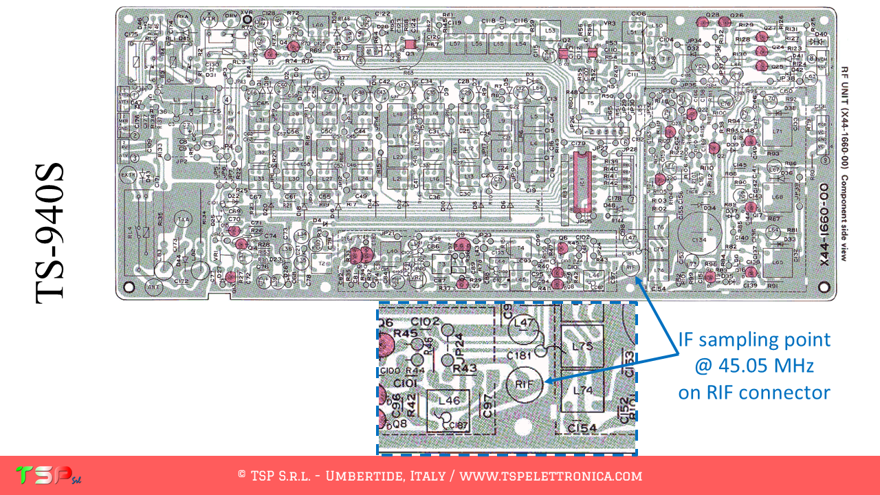
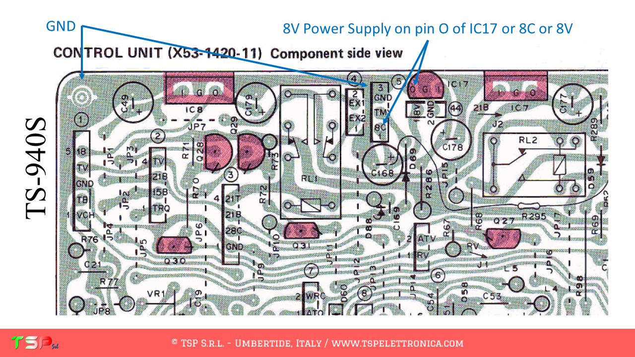
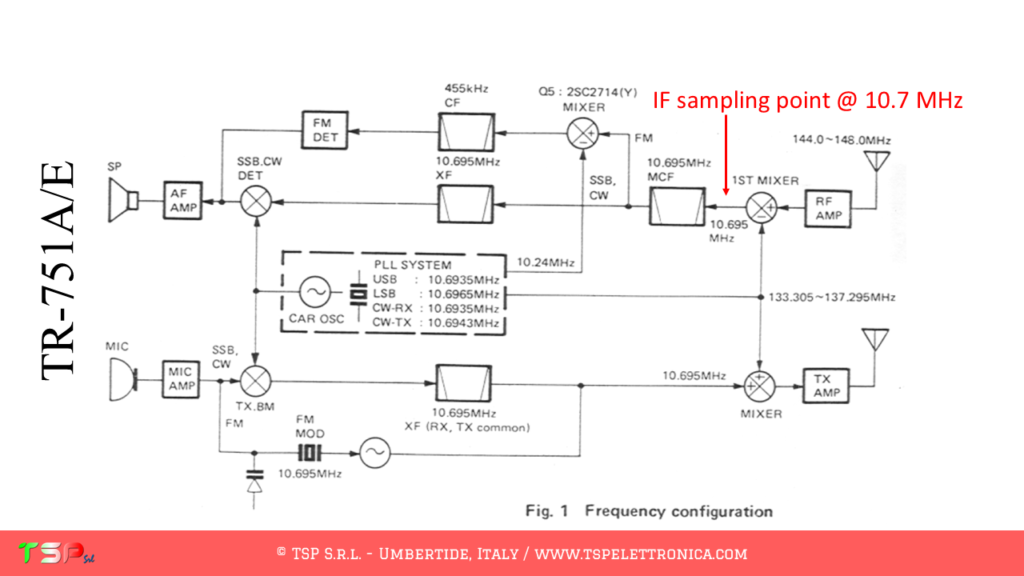
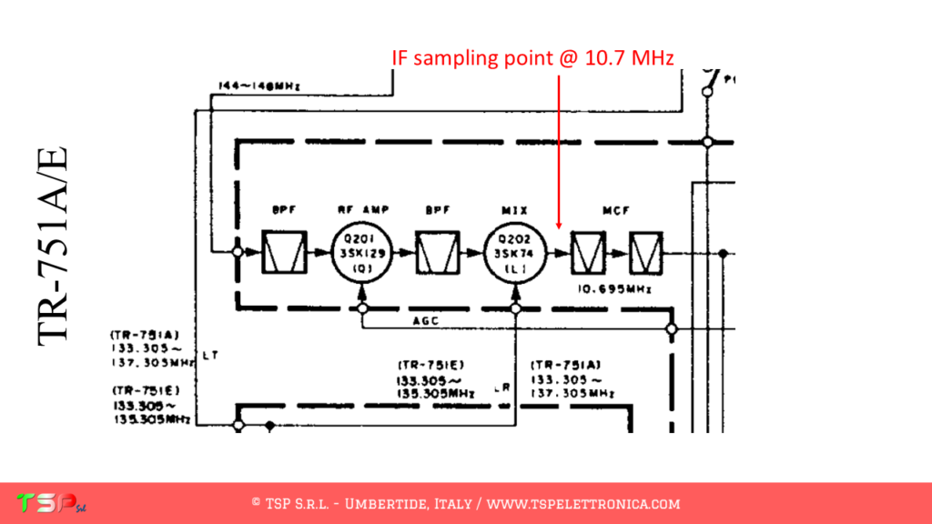
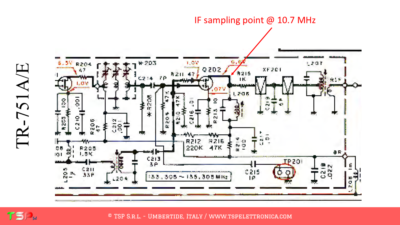
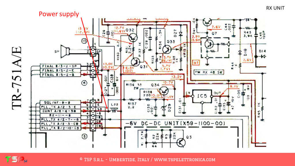
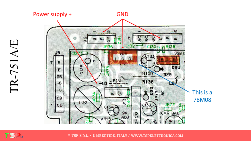
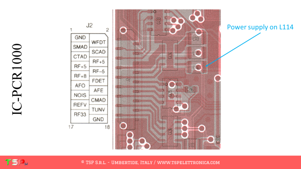
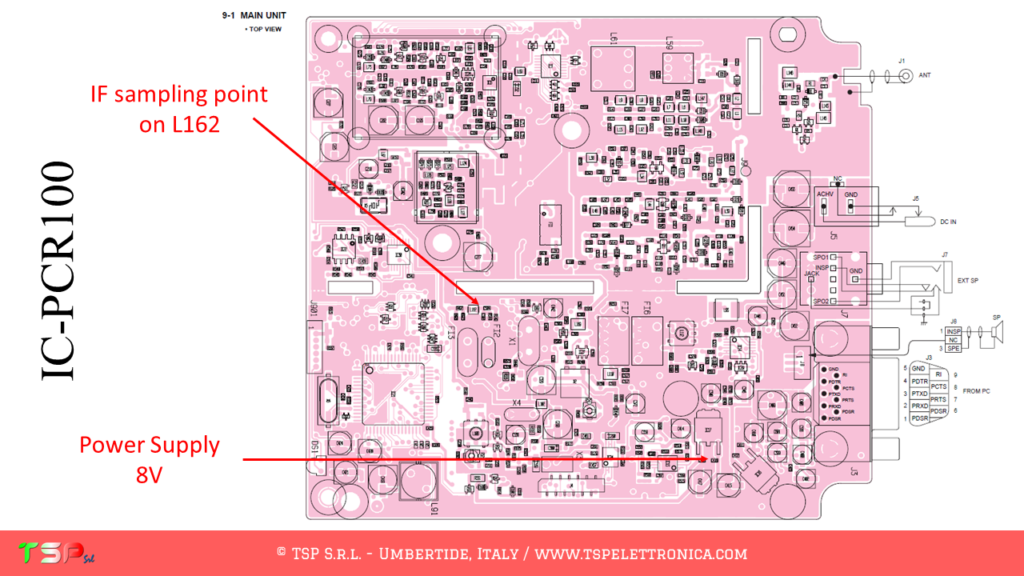
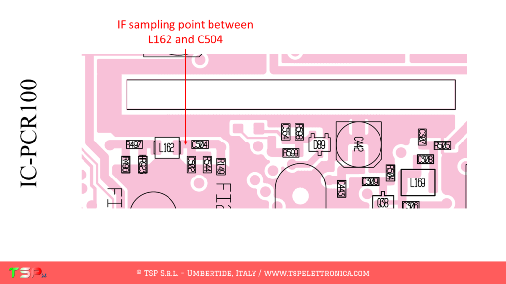
Let’s start by analyzing the wiring diagram. The procedure is always the same: we have to find the first mixer, the PTT and where to take the power supply. From the following images everything will appear clear.

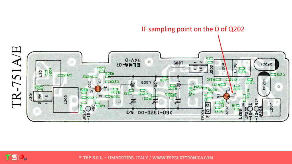
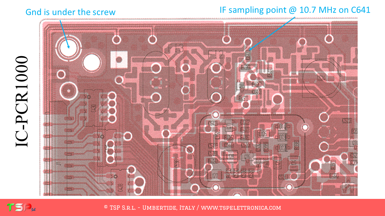
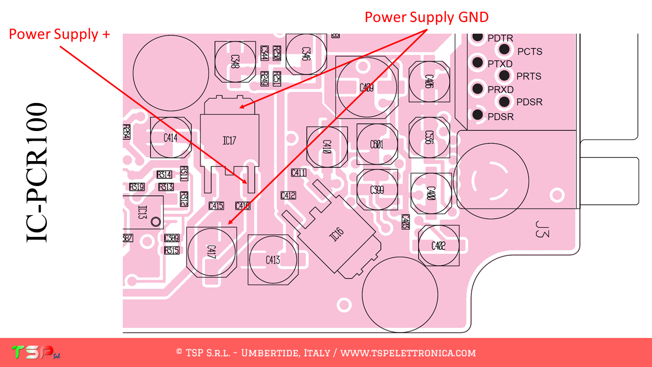
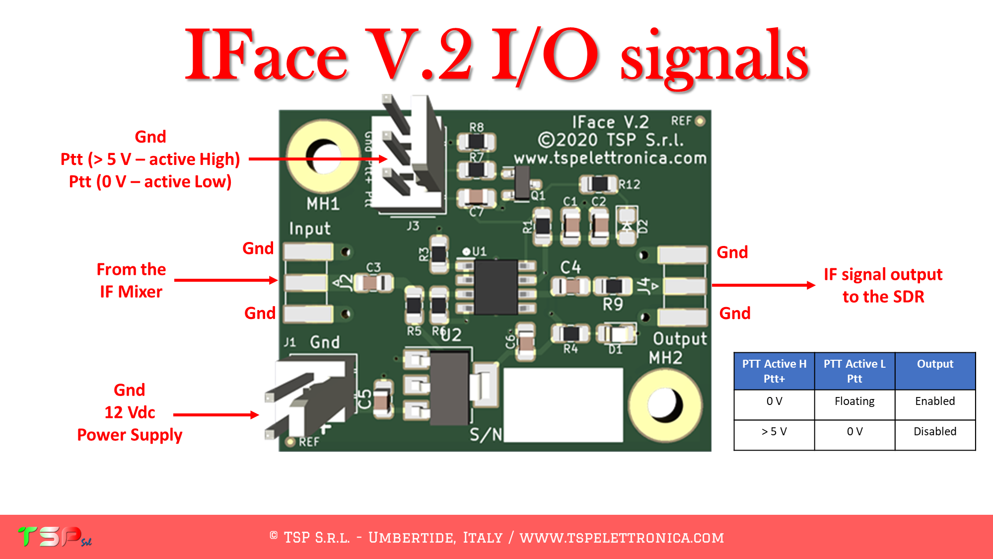
At this point we have to locate the points where we connect the electric cables to the IFace. The following images show where to take the various signals.

To buy an IFace please use one of the buttons below.

ATTENTION: Though installing the IFace is not difficult, you do this at your own risk. TSP S.r.l. is not responsible for any damage, unwanted side-effects or whatever.

For more information do not hesitate to write us.
Have fun!

TS-940S with SDR panadapter

Our buffer interface named IFace can be used to add an SDR panadapter to the Kenwood TS-940S.

The operations to be carried out are very simple, it is sufficient to obtain from its wiring diagram the information on the points where the IF signal has to be taken. This radio uses several mixers, we are interested in the first of the reception chain as it gives us a broadband signal. The IF frequency is 45.05 MHz. The following images show the block diagram of the radio and where to get the IF signal.

The following images show the portions of the schematic diagram of the RX UNIT where we can see the exact points where to sample the IF signal and the power supply.

We now proceed to identify the exact points on the printed circuit board where to take the IF signal to be sent to the IFace. The following images show the sampling point for the IF signal and for the power supply for the buffer interface.

The use of PTT signal is not required, RX and TX signals are separated.

In order to purchase an IFace use the buttons below.

ATTENTION: Though installing the IFace is not difficult, you do this at your own risk. TSP S.r.l. is not responsible for any damage, unwanted side-effects or whatever.

For more information, do not hesitate to write to us using the form below.
Have fun!

From zero to Arduino® – Lecture 3

We’re sorry, this content is not yet available in English. If interested in this topic, please contact us and we’ll try to produce an english version of this online course.

In the meanwhile, you can try to attend this online lectures thanks to the subtitles.

Last but not least, do not forget to subscribe to our YouTube channel (click here) and to activate the notifications (click on the bell).

Enjoy 😉

From zero to Arduino® – Lecture 2

We’re sorry, this content is not yet available in English. If interested in this topic, please contact us and we’ll try to produce an english version of this online course.

In the meanwhile, you can try to attend this online lectures thanks to the subtitles.

Last but not least, do not forget to subscribe to our YouTube channel (click here) and to activate the notifications (click on the bell).

Enjoy 😉

TR-751A/E with SDR panadapter

Our buffer interface named IFace can be used to add an SDR panadapter to the Kenwood TR-751A/E.

The operations to be carried out are very simple, it is sufficient to obtain from its wiring diagram the information on the points where the IF signal has to be taken. This radio uses several mixers, we are interested in the first of the reception chain as it gives us a broadband signal. The IF frequency is 10.7 MHz. The following images show the block diagram of the radio and where to get the IF signal.

The following images show the portions of the schematic diagram of the RX UNIT where we can see the exact points where to sample the IF signal and the power supply.

We now proceed to identify the exact points on the printed circuit board where to take the IF signal to be sent to the IFace. The following images show the sampling point for the IF signal and for the power supply for the buffer interface.

The use of PTT signal is not required, RX and TX signals are separated.

For a deeper understanding of the installation, please watch the following video.

In order to purchase an IFace use the buttons below.

ATTENTION: Though installing the IFace is not difficult, you do this at your own risk. TSP S.r.l. is not responsible for any damage, unwanted side-effects or whatever.

For more information, do not hesitate to write to us using the form below.
Have fun!

IC-PCR1000 with SDR panadapter

Our buffer interface named IFace can be used to add an SDR panadapter to the Icom IC-PCR1000.

The operations to be carried out are very simple, it is sufficient to obtain from its wiring diagram the information on the points where the IF signal has to be taken. This radio uses several mixers, in this case, we are interested in the second one of the reception chain as it still gives us a broadband signal. The IF frequency is 10.7 MHz. The following images show the block diagram of the radio and where to get the IF signal.

The following images show the portions of the schematic diagram of the RF UNIT where we can see the exact points where to sample the IF signal and the power supply.

We now proceed to identify the exact points on the printed circuit board where to take the IF signal to be sent to the IFace. The following images show the sampling point for the IF signal and for the power supply for the buffer interface.

The use of PTT signal is not required, this is a receiver.

In order to purchase an IFace use the buttons below.

ATTENTION: Though installing the IFace is not difficult, you do this at your own risk. TSP S.r.l. is not responsible for any damage, unwanted side-effects or whatever.

For more information, do not hesitate to write to us using the form below.
Have fun!

IC-PCR100 with SDR panadapter

Our buffer interface named IFace can be used to add an SDR panadapter to the Icom IC-PCR100.

The operations to be carried out are very simple, it is sufficient to obtain from its wiring diagram the information on the points where the IF signal has to be taken. This radio uses several mixers, in this case, we are interested in the second one of the reception chain as it still gives us a broadband signal. The IF frequency is 10.7 MHz. The following images show the block diagram of the radio and where to get the IF signal.

The following images show the portions of the schematic diagram of the RF UNIT where we can see the exact points where to sample the IF signal and the power supply.

We now proceed to identify the exact points on the printed circuit board where to take the IF signal to be sent to the IFace. The following images show the sampling point for the IF signal and for the power supply for the buffer interface.

The use of PTT signal is not required, this is a receiver.

In order to purchase an IFace use the buttons below.

ATTENTION: Though installing the IFace is not difficult, you do this at your own risk. TSP S.r.l. is not responsible for any damage, unwanted side-effects or whatever.

For more information, do not hesitate to write to us using the form below.
Have fun!

From zero to Arduino® – Lecture 1

We’re sorry, this content is not yet available in English. If interested in this topic, please contact us and we’ll try to produce an english version of this online course.

In the meanwhile, you can try to attend this online lectures thanks to the subtitles.

Last but not least, do not forget to subscribe to our YouTube channel (click here) and to activate the notifications (click on the bell).

Enjoy 😉

TS-130S/V with SDR panadapter

Our buffer interface named IFace can be used to add an SDR panadapter to the Kenwood TS-130S/V.

The operations to be carried out are very simple, it is sufficient to obtain from its wiring diagram the information on the points where the IF signal has to be taken. This radio uses several mixers, we are interested in the first of the reception chain as it gives us a broadband signal. The IF frequency is 8.830 MHz. The following image shows the block diagram of the radio and where to get the IF signal.

The following image shows the portions of the schematic diagram of the TX-RX UNIT where we can see the exact points where to sample the IF signal and the power supply.

We now proceed to identify the exact points on the printed circuit board where to take the IF signal to be sent to the IFace. The following images show the sampling point for the IF signal and for the power supply for the buffer interface.

The use of PTT signal is not required, RX and TX signals are separated.

In order to purchase an IFace use the buttons below.

ATTENTION: Though installing the IFace is not difficult, you do this at your own risk. TSP S.r.l. is not responsible for any damage, unwanted side-effects or whatever.

For more information, do not hesitate to write to us using the form below.
Have fun!

From zero to Arduino® – Lecture 0

We’re sorry, this content is not yet available in English. If interested in this topic, please contact us and we’ll try to produce an english version of this online course.

In the meanwhile, you can try to attend this online lecture thanks to the subtitles.

Last but not least, do not forget to subscribe to our YouTube channel (click here) and to activate the notifications (click on the bell).

Enjoy 😉

© TSP S.r.l. | VAT IT03137540542 | V.le Unità d'Italia 36, 06019 Umbertide, ITALY