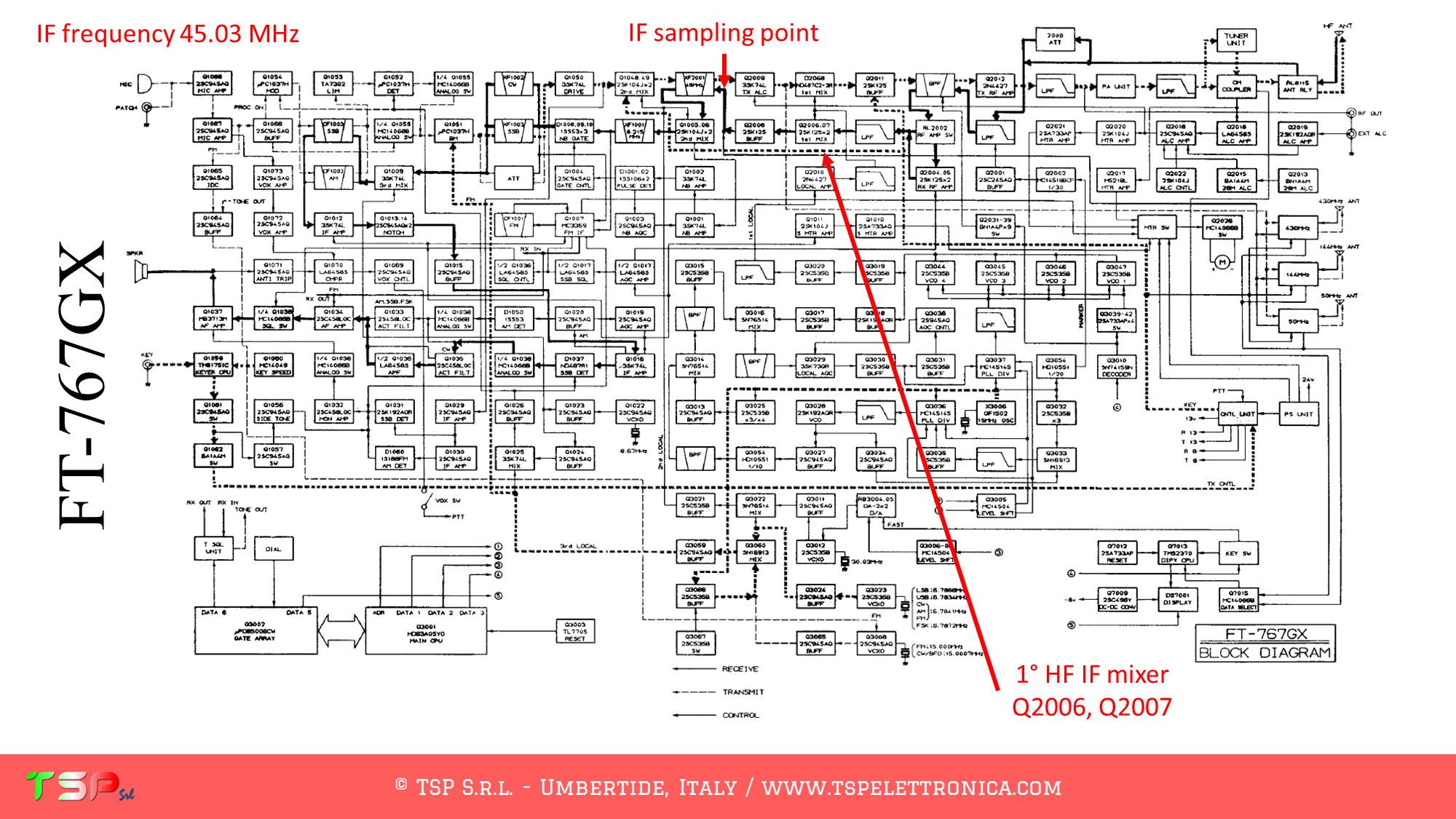
The operations to be carried out are very simple, it is sufficient to obtain from its wiring diagram the information on the points where the IF signal has to be taken. This radio uses more than one mixer. The IF frequency of the first one is 45.03 MHz and our SDR panadapter will be tuned to this. The following image shows the block diagram of the radio and where to get the IF signal.
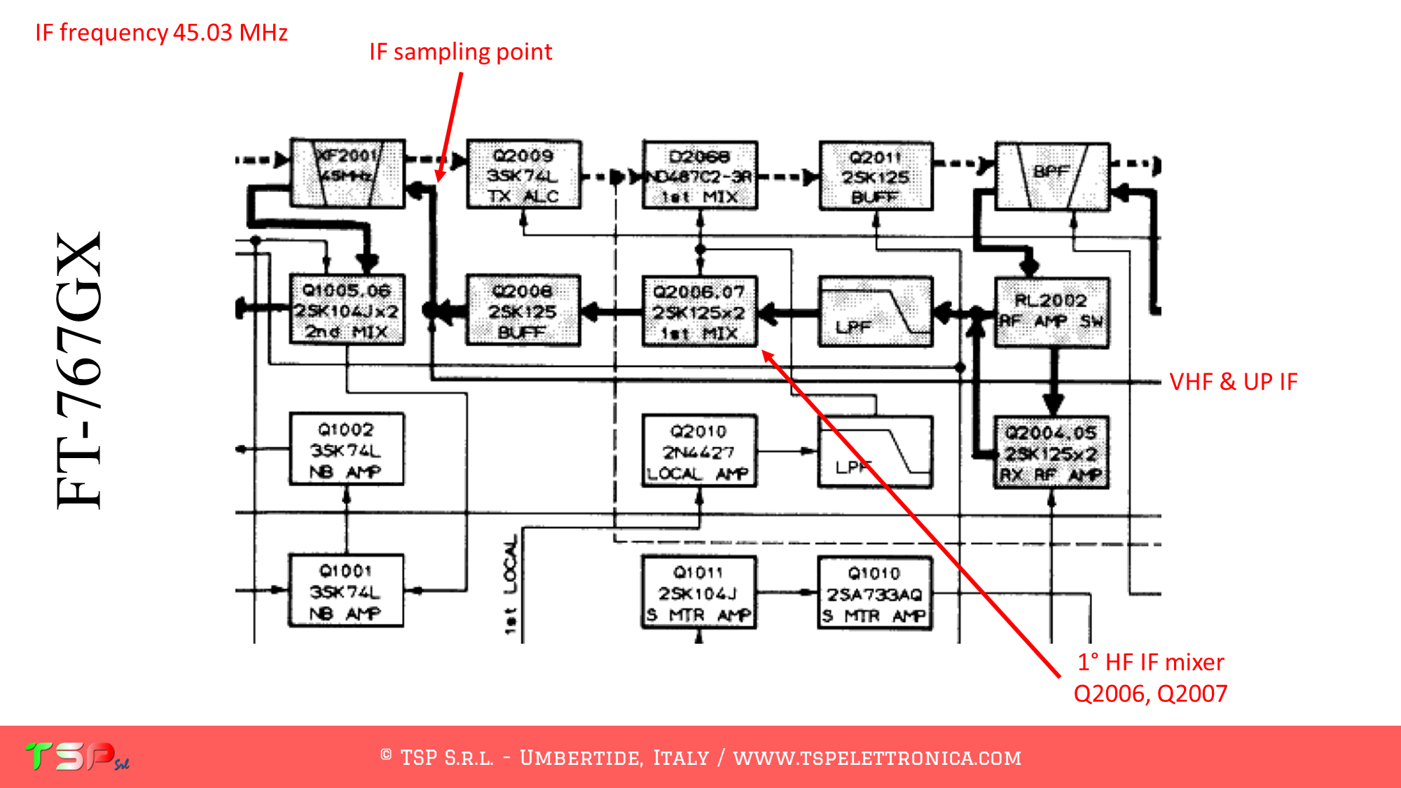
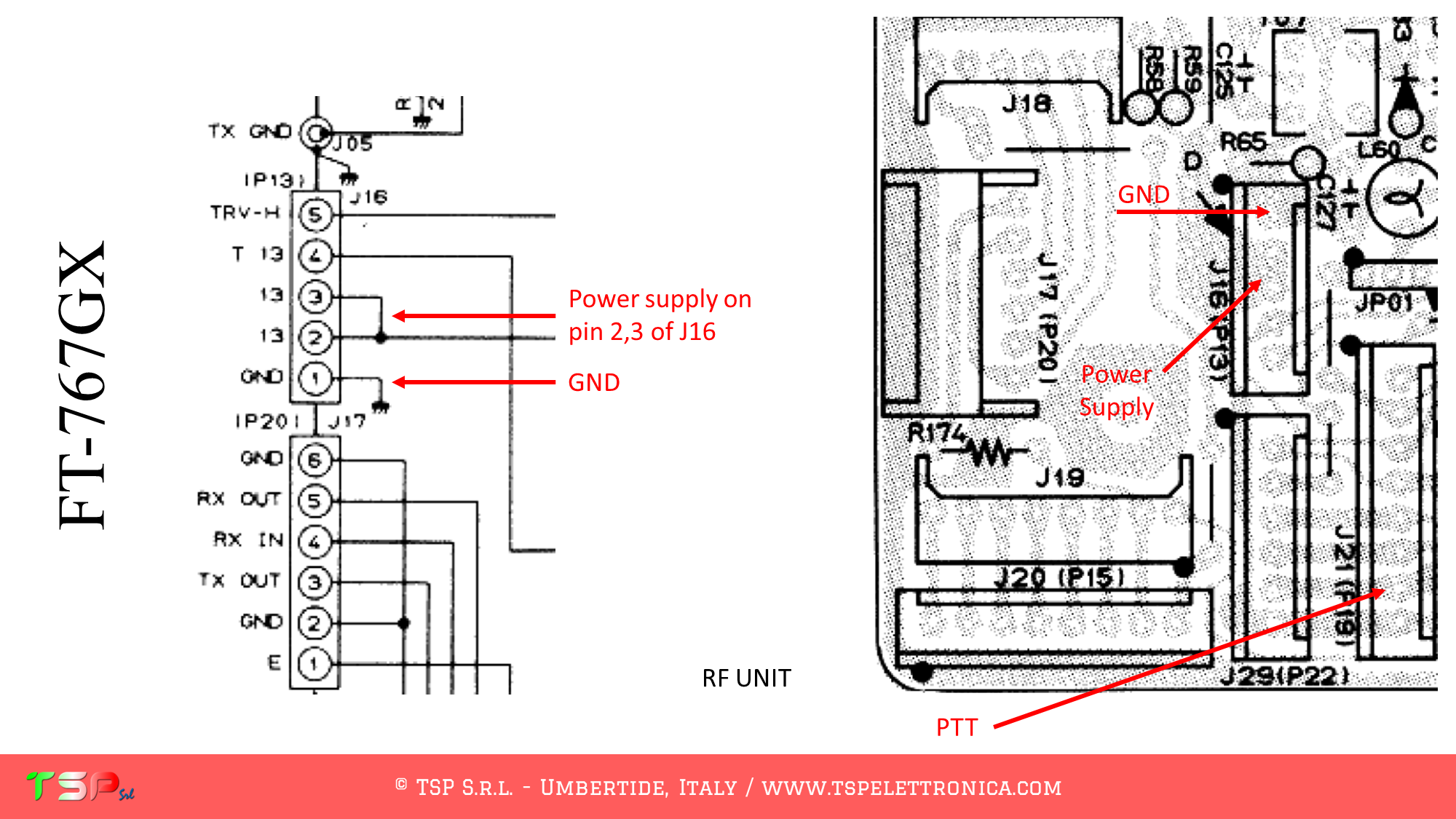
The following images show the portions of the schematic diagram of the RF UNIT where we can see the exact points where to sample the IF signal, the PTT+ (active high) and the power supply.
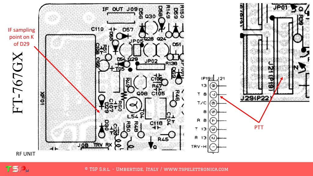
We now proceed to identify the exact points on the printed circuit board where to take the IF signal to be sent to the IFace. The following images show the sampling point for the IF signal, for the PTT+, and for the power supply for the buffer interface.
The use of PTT signal is required because some circuitry is shared between the TX and the RX signal paths.
In order to buy an IFace use the buttons below.
ATTENTION: Though installing the IFace is not difficult, you do this at your own risk. TSP S.r.l. is not responsible for any damage, unwanted side-effects or whatever.
For more information, do not hesitate to write to us using the form below. Have fun!
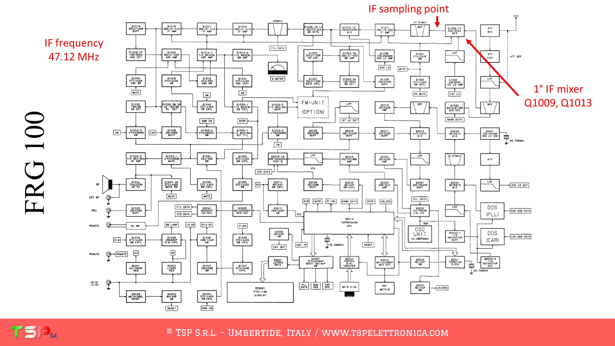
The operations to be carried out are very simple, it is sufficient to obtain from its wiring diagram the information on the points where the IF signal has to be taken. This radio uses more than one mixer. The IF frequency of the first one is 47.12 MHz and our SDR panadapter will be tuned to this. The following image shows the block diagram of the radio and where to get the IF signal.
The following images show the portions of the schematic diagram of the IF UNIT where we can see the exact points where to sample the IF signal and the power supply.
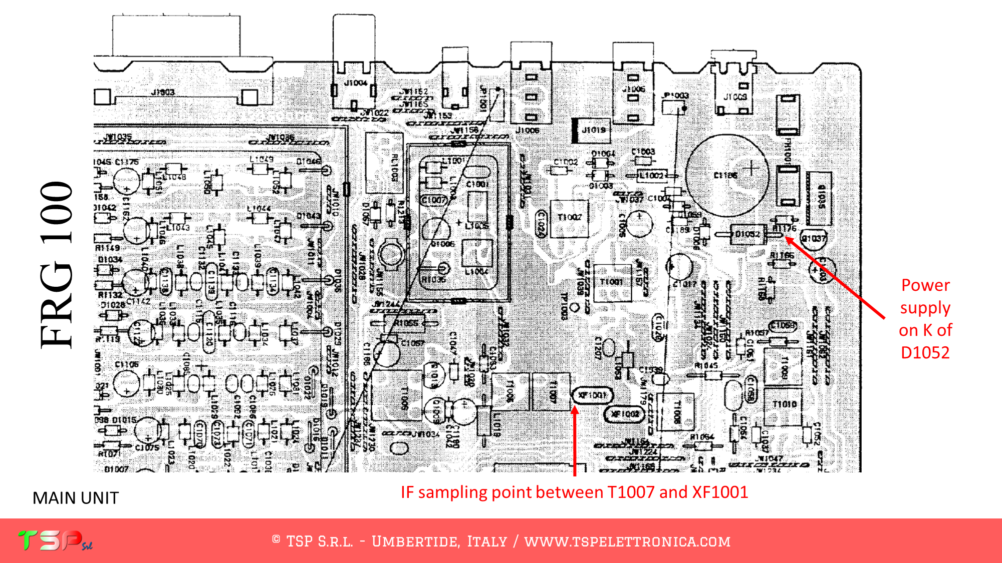
We now proceed to identify the exact points on the printed circuit board where to take the IF signal to be sent to the IFace. The following images show the sampling point for the IF signal and for the power supply for the buffer interface.
The use of PTT signal is not required, this is a receiver.
In order to buy an IFace use the buttons below.
ATTENTION: Though installing the IFace is not difficult, you do this at your own risk. TSP S.r.l. is not responsible for any damage, unwanted side-effects or whatever.
For more information, do not hesitate to write to us using the form below. Have fun!
The operations to be carried out are very simple, it is sufficient to obtain from its wiring diagram the information on the points where the IF signal has to be taken. This radio uses one mixer only for the receptio. The IF frequency is 10.7 MHz and our SDR panadapter will be tuned to this. The following image shows the block diagram of the radio and where to get the IF signal.
The following images show the portions of the schematic diagram of the IF UNIT where we can see the exact points where to sample the IF signal and the power supply.
We now proceed to identify the exact points on the printed circuit board where to take the IF signal to be sent to the IFace. The following images show the sampling point for the IF signal and for the power supply for the buffer interface.
The use of PTT signal is not required, RX and TX signals are separated.
In order to buy an IFace use the buttons below.
ATTENTION: Though installing the IFace is not difficult, you do this at your own risk. TSP S.r.l. is not responsible for any damage, unwanted side-effects or whatever.
For more information, do not hesitate to write to us using the form below. Have fun!
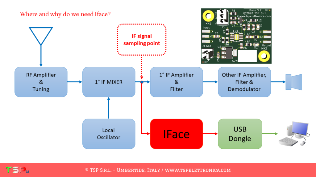
Below are the notes relating to the installation of the IFace interface inside the Kenwood TS-870S of IZ0ABD Francesco. In general, this work is carried out to be able to extract an IF signal from inside the radio so that it can be used to create an SDR panadapter. In general, the application scheme is shown in the following image.
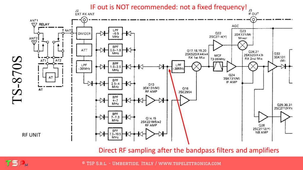
In this case, however, the installation to extract the IF after the first receiving mixer produced unsatisfactory results as, as stated by the manufacturer, the nominal output frequency varies as the filter settings vary. In practice, by varying the width of the IF filters there is a shift in the IF frequency and this complicates demodulation by SDR (each shift in frequency of the RF signal results in a corresponding variation of the BF one – at least for most of the modulations).
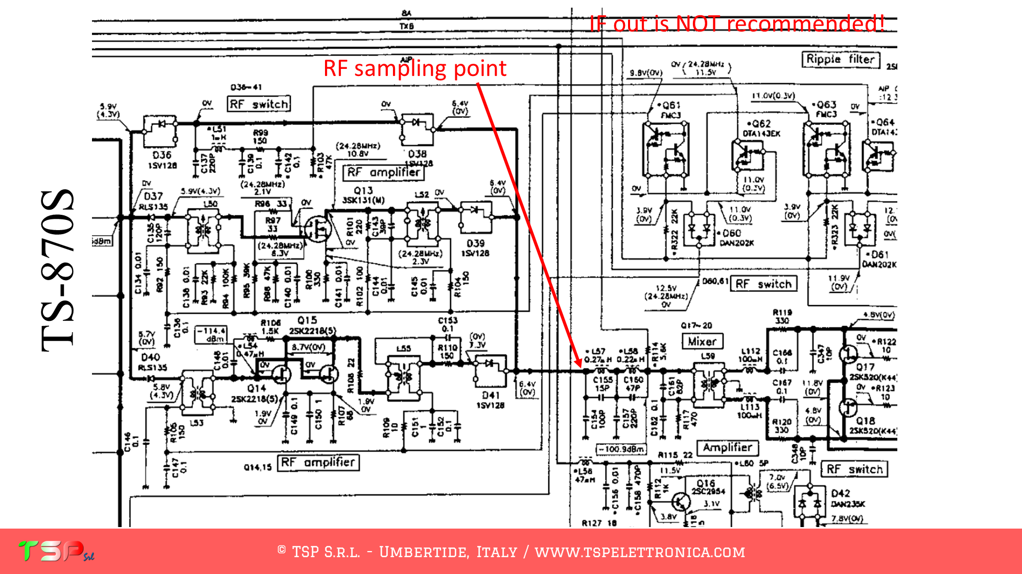
For this reason, another strategy was adopted, thus taking the signal to be sent to the SDR receiver immediately before the first reception mixer. Obviously, in this way, the IF signal is not taken but the RF signal, even if suitably filtered by the radio band filters. Refer to the following images for the details of this operation. The use of the IFace card is always necessary as we cannot connect a low impedance load (50 Ohm) in parallel to the radio circuits, a buffer is required.
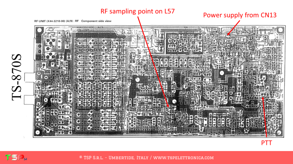
The RF signal arriving from the antenna is taken upstream of a low-pass filter: from the following diagram, it is possible to identify the exact point where the input of the IFace board will be connected. This is located downstream of diodes D38, D39, and D41 and upstream of the LPF circuit consisting of components L57, C154, C155, and others.
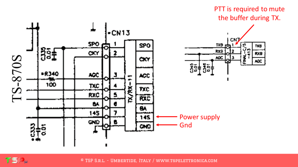
The task of the IFace buffer card is to deliver the power needed to drive the SDR receiver circuits correctly: in general, the intensities of the signals of interest are small fractions of mW. During transmission, on the other hand, there are powers of the order of W or even more, and this can be a problem for the external receiver, especially now that it is working in isofrequency with the radio. Therefore it is good to use the PTT signal to disable the buffer, a unique feature of the IFace. It is therefore necessary to identify the point inside the radio where to take this signal. Nothing could be easier, the TX8 signal is present on the CN7 connector and this is active only during transmission.
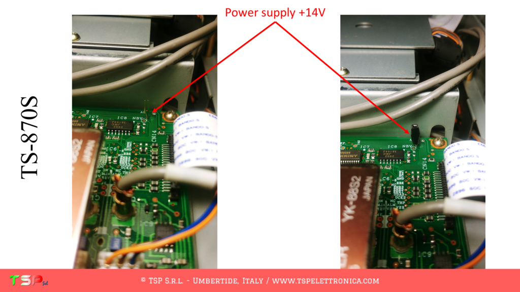
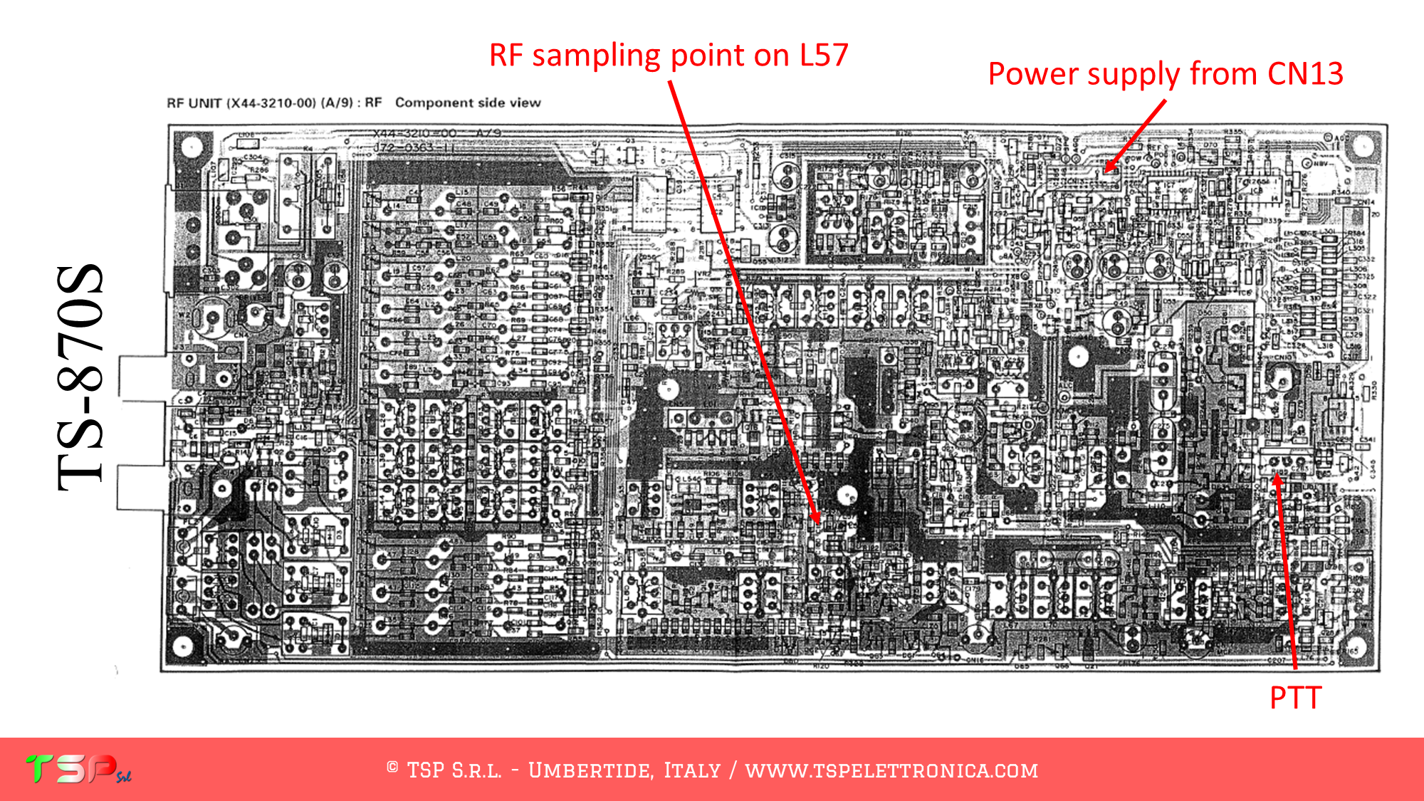
Having to supply power, the IFace must also be adequately powered. From connector CN13 it is possible to obtain the voltage required by pins 14S and GND.
Below are some images useful to identify the points on the RF UNIT where to take the various signals: RF, PTT, and power supply.
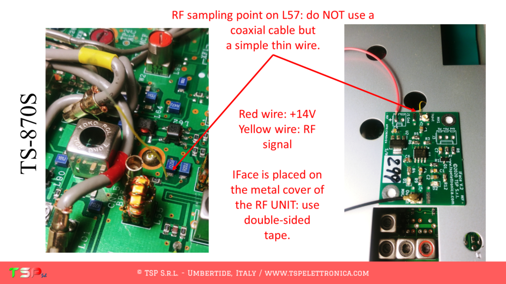
This image shows how to connect the RF signal from the RF UNIT to the IFace. A thin (0.14 mm) conductor covered in yellow plastic is used. As highlighted, it is not recommended to use a coaxial cable because it introduces a not negligible capacitance in parallel to the components of the LPF 30 MHz circuit and would modify their performance.
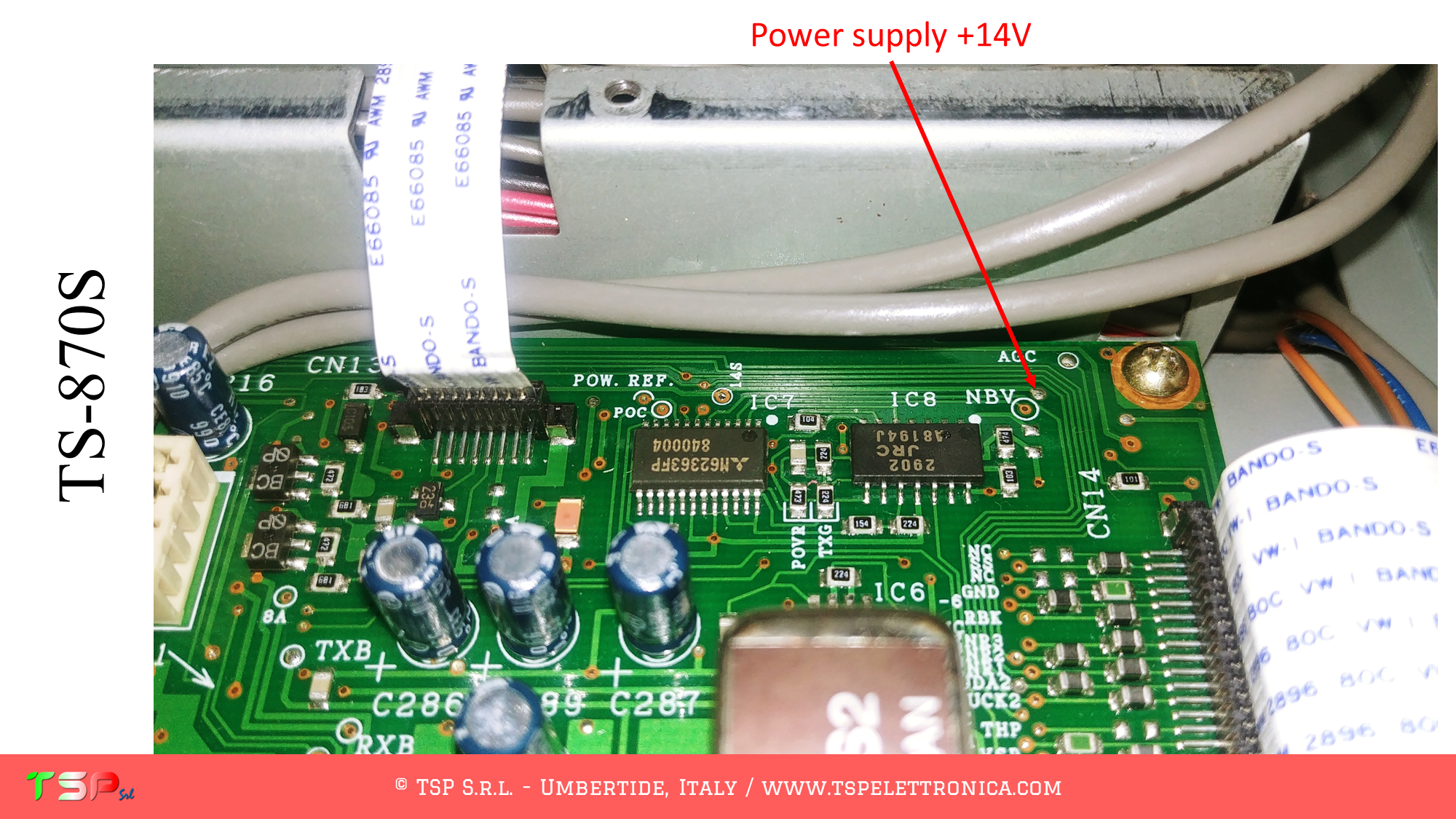
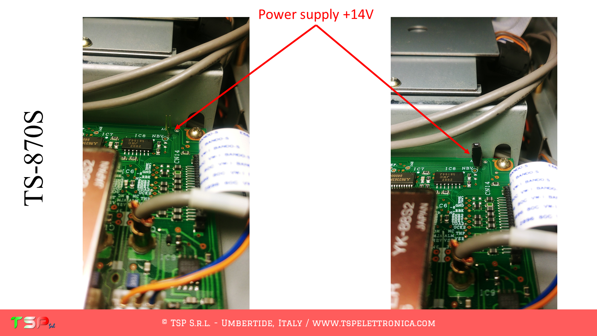
The power cable of the board is shown in red and in the following two images it is highlighted where to draw the necessary energy.
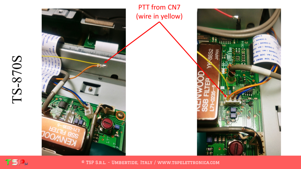
The PTT signal is available on the CN7 connector. You can recognize it because it is the one on the side of the IF filter for the SSB and comes to it via an orange conductor. What we have to do is bring this signal to the IFace and it has been done by means of a thin conductor (also in this case yellow in color) placed in parallel directly in the connector (the terminal has been removed from its housing, the thin metal wire wound on it and then reinserted).
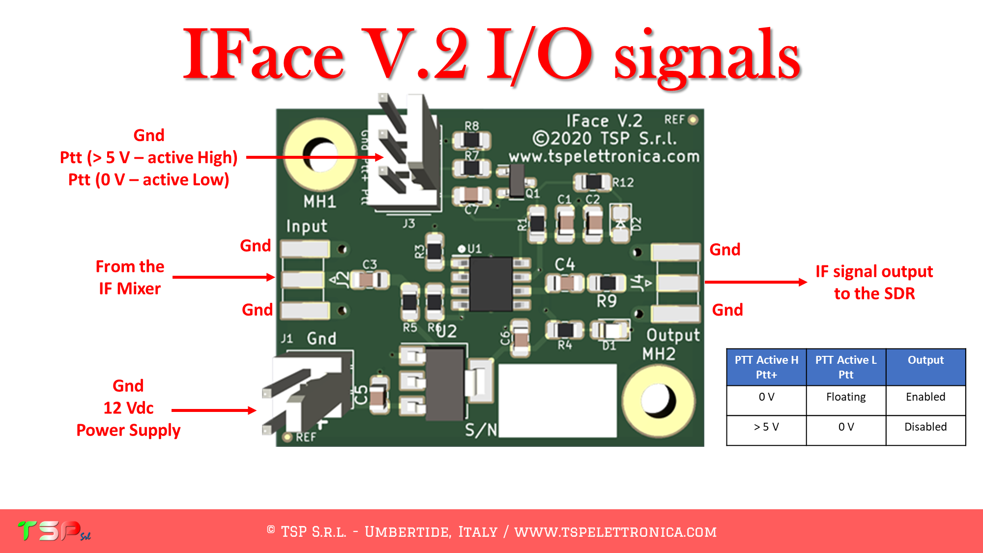
At this point, the PTT is connected to the corresponding input on the IFace. Pay attention to which of the three pins is used, the central one is relative to the high active PTT, the left one (in the photo) is relative to the low active PTT, the third is the return to the ground (GND).
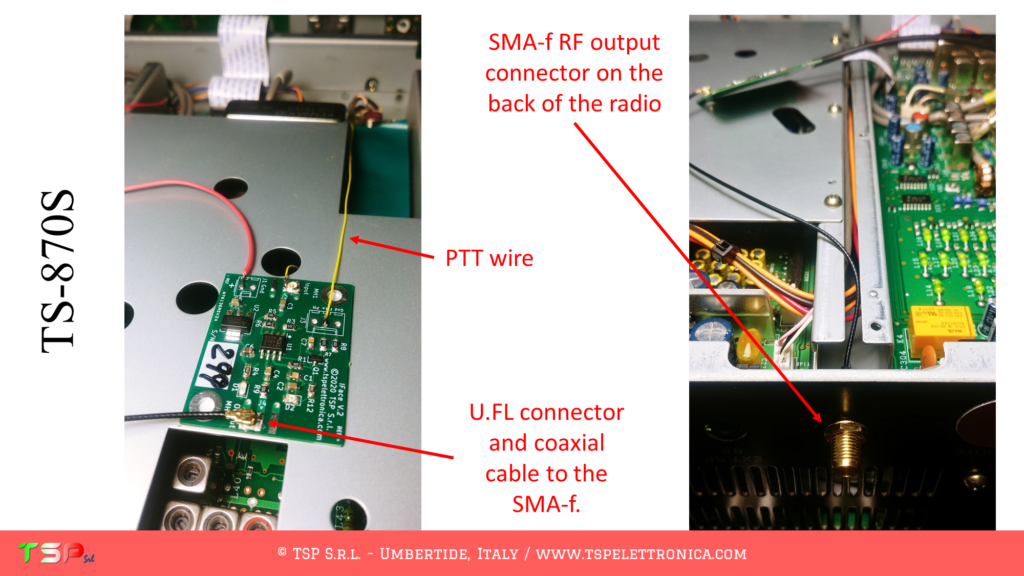
In the photographs in the following image you can also see where the IFace board is fixed (on the metal covering the RF UNIT – double-sided adhesive was used) and the SMA-f connector for output of the RF signal. To this comes the output signal through a thin coaxial cable terminated, on the opposite side, with a U.FL connector. The specific PCB connector has been soldered to the IFace (both are supplied in the corresponding kit if purchased).
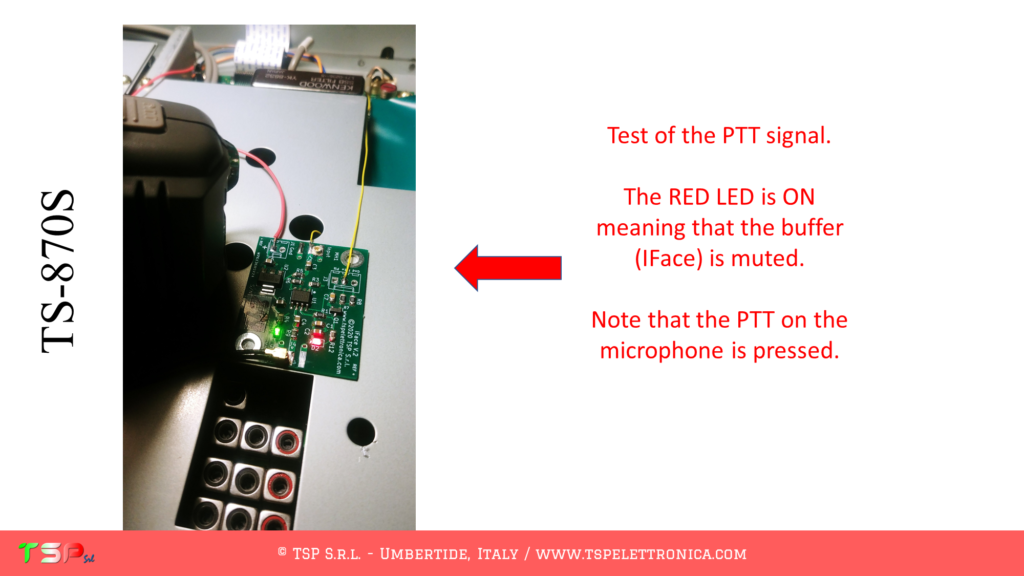
Finally, this image shows that when you press the PTT on the microphone, the corresponding LED on the IFace lights up (it is the one in red).
It should be noted that this installation involves the isofrequency use of the external SDR receiver. This means that we will have our software set up to receive exactly what the radio is receiving, whereas if we made it work on the IF we would have different settings and also a different functioning. In fact, it has been verified that the IFace buffer correctly disables the flow of energy during transmission, but despite this, the external SDR receiver still picks up a good amount of RF signal (not from the IFace but directly from the environment in which it is located) and must force adjust its gain control circuits by reducing it by a lot. This, returning to reception, has repercussions in a short period (about 1s) in which the SDR receiver is desensitized, then the AGC does its duty and everything returns to normal. Working in IF all this does not happen because the transmission frequency of the radio is different from that of reception of our SDR.
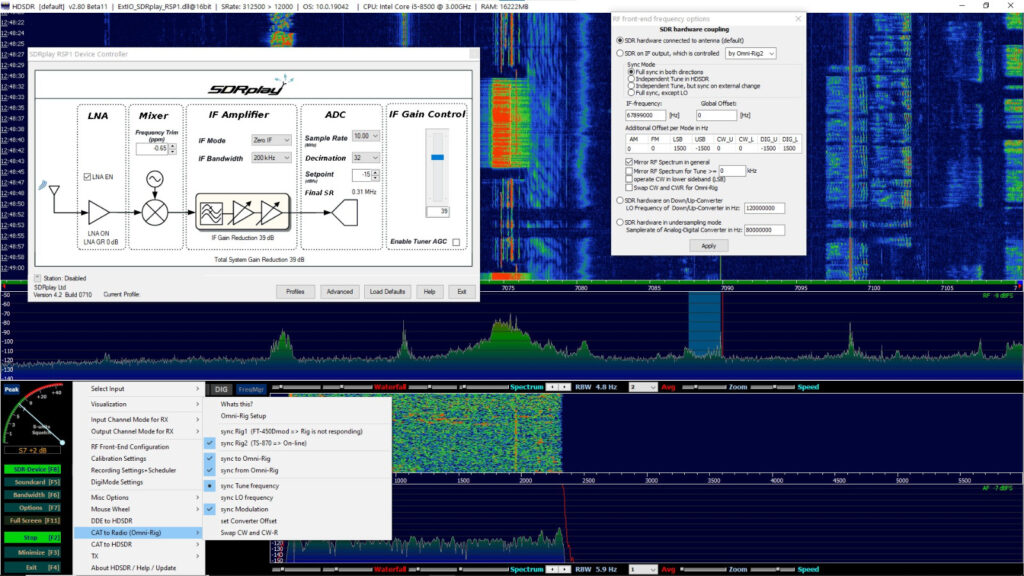
Below are a couple of screenshots related to using HDSDR and an RSP1 to realize the panadapter function together with the TS-870S.
The image above highlights the settings to be used. You can see the use of decimation (very important) and that the SDR receiver works exactly in isofrequency, not on IF.
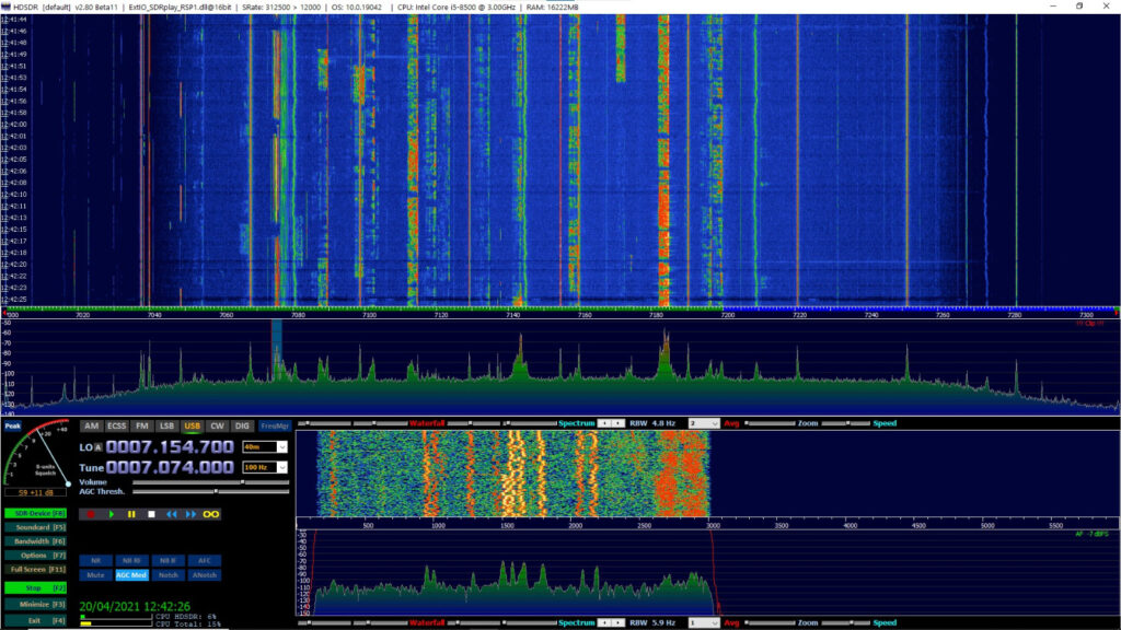
The image above shows, for those who are curious, which band is visible on the panadapter with the settings shown above.
To purchase an IFace you can use the following buttons.
ATTENTION: Although the installation of IFace 2 is not difficult, it is done at your own risk. TSP S.r.l. is not responsible for any damage, unwanted side effects, or anything else.
The operations to be carried out are really very simple, it is sufficient to obtain from its wiring diagram the information on the points where to take the RF signals. In this case, in fact, we will not pick up the IF signal because this radio has such an architecture that the IF frequency is not constant but varies as the working conditions vary. So what we will get is a replica of the signal arriving from the antenna, suitably filtered by the band filters. The frequency that we will tune with our SDR receiver will be the same as that of the radio and not that of the IF. The following image shows the block diagram of the radio and where to take the IF signal.
The following images show the exact points in the wiring diagram where to take the RF signal, power supply and PTT. This is required to limit the RF signal entering the SDR panadapter during transmission.
The points on the PCB where to connect the IFace board are shown below: the RF signal, the power supply and the PTT are required: do not forget the return to GND of the power supply (which can also be obtained from the coaxial connector if in contact with the radio chassis).
The use of the PTT signal is required in order to disable the buffer as the SDR receiver will be tuned to the same transmission frequency and it is therefore necessary to protect it from signal excesses.
In order to buy an IFace use the buttons below.
ATTENTION: Though installing the IFace is not difficult, you do this at your own risk. TSP S.r.l. is not responsible for any damage, unwanted side-effects or whatever.
For more information, do not hesitate to write to us using the form below. Have fun!
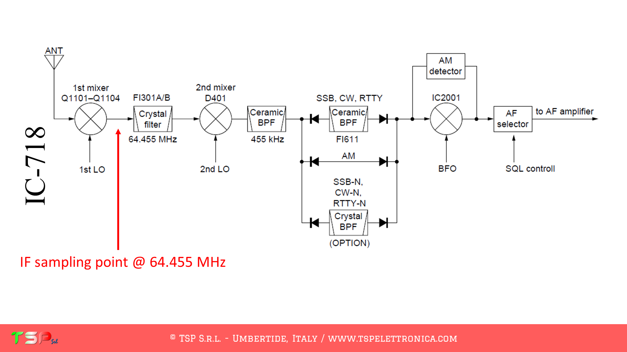
The operations to be carried out are very simple, it is sufficient to obtain from its wiring diagram the information on the points where the IF signal has to be taken. This radio uses several mixers and we are interested in the first IF frequency (this makes it easier to operate the panadapter). The IF frequency chosen is 64.455 MHz and our SDR panadapter will be tuned to this. The following image shows the block diagram of the radio and where to get the IF signal.
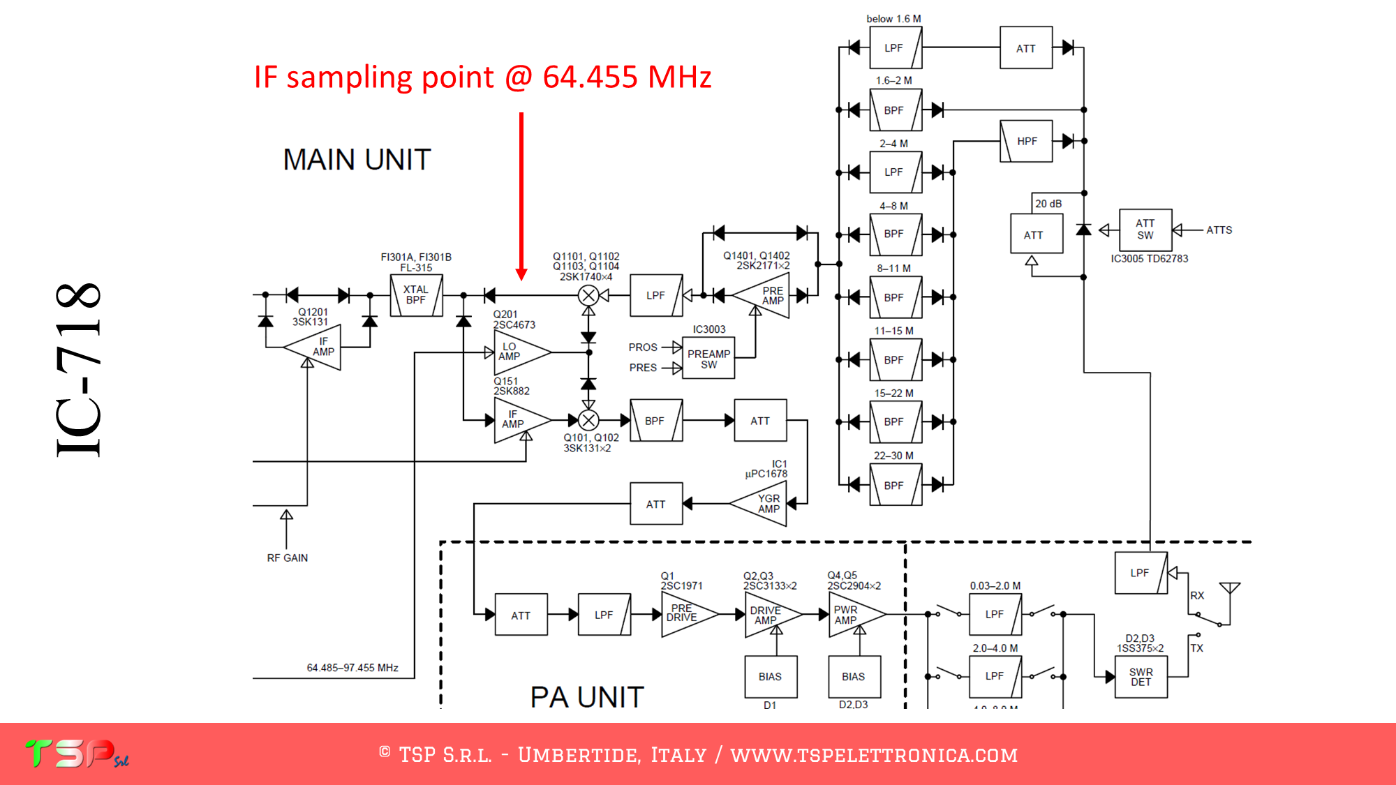
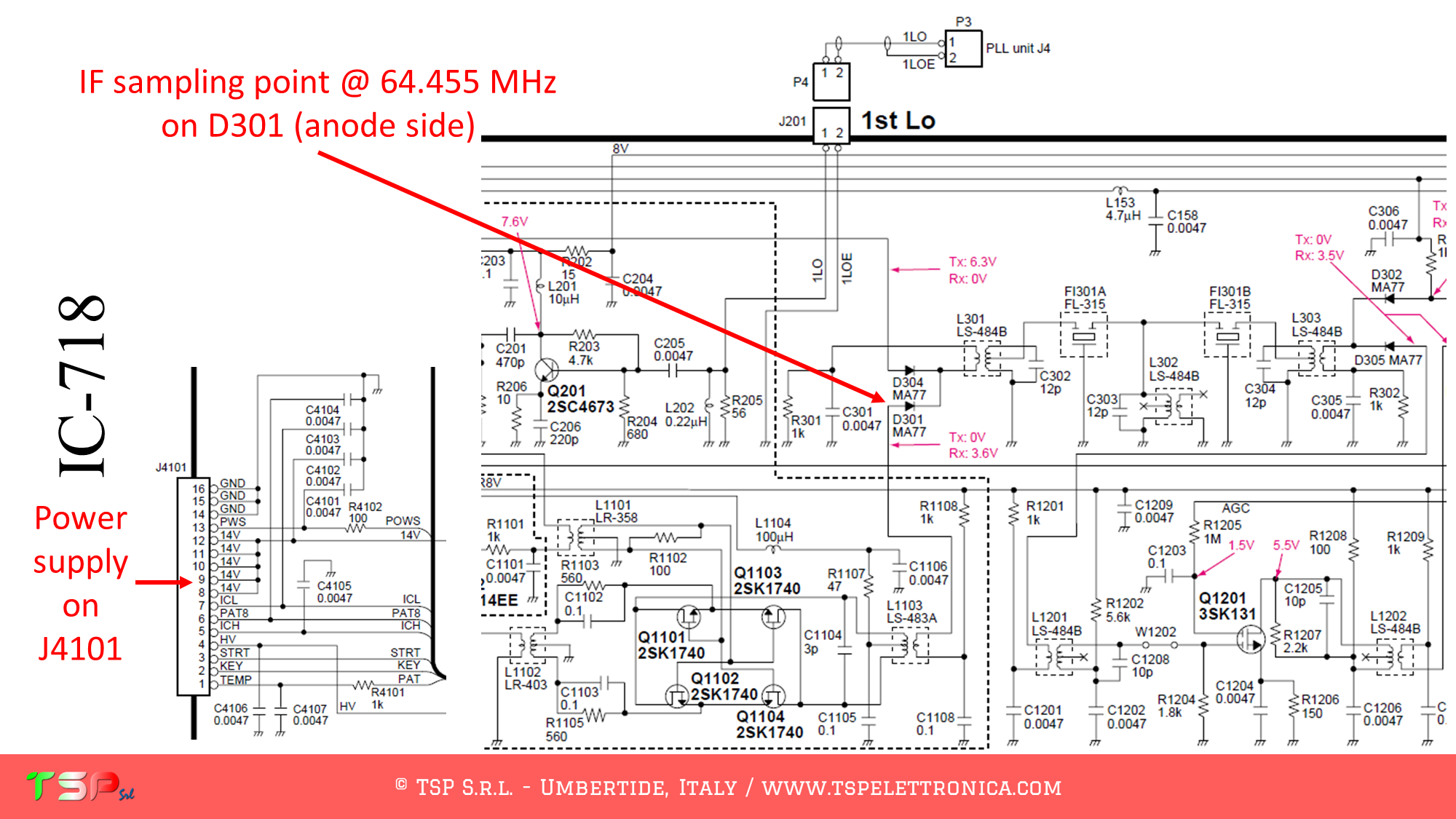
The following image shows the portions of the schematic diagram of the IF UNIT where we can see the exact points where to sample the IF signal and the power supply.
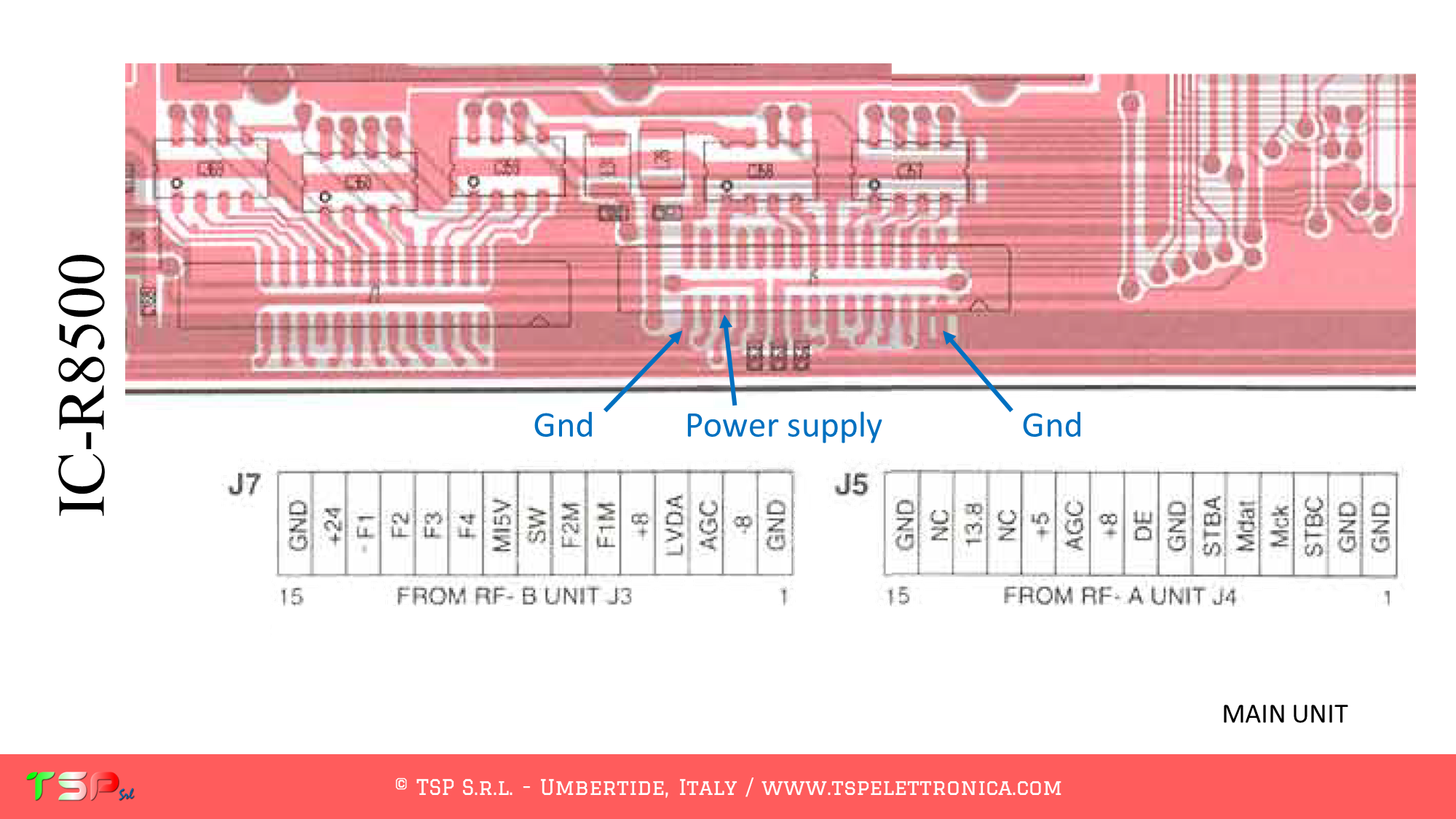
We now proceed to identify the exact points on the printed circuit board where to take the IF signal to be sent to the IFace. The following images show the sampling point for the IF signal and for the power supply for the buffer interface.
The use of PTT signal is not required because RX and TX signals are separated.
In order to buy an IFace use the buttons below.
ATTENTION: Though installing the IFace is not difficult, you do this at your own risk. TSP S.r.l. is not responsible for any damage, unwanted side-effects or whatever.
For more information, do not hesitate to write to us using the form below. Have fun!
The operations to be carried out are very simple, it is sufficient to obtain from its wiring diagram the information on the points where the IF signal has to be taken. This radio uses several mixers with complex architecture. We are interested in the second IF frequency (this makes it easier to operate the panadapter). The IF frequency chosen is 10.7 MHz and our SDR panadapter will be tuned to this. The following image shows the block diagram of the radio and where to get the IF signal.
The following image shows the portions of the schematic diagram of the IF UNIT where we can see the exact points where to sample the IF signal and the power supply.
We now proceed to identify the exact points on the printed circuit board where to take the IF signal to be sent to the IFace. The following images show the sampling point for the IF signal and for the power supply for the buffer interface.
The use of PTT signal is not required because this radio is a receiver.
In order to buy an IFace use the buttons below.
ATTENTION: Though installing the IFace is not difficult, you do this at your own risk. TSP S.r.l. is not responsible for any damage, unwanted side-effects or whatever.
For more information, do not hesitate to write to us using the form below. Have fun!
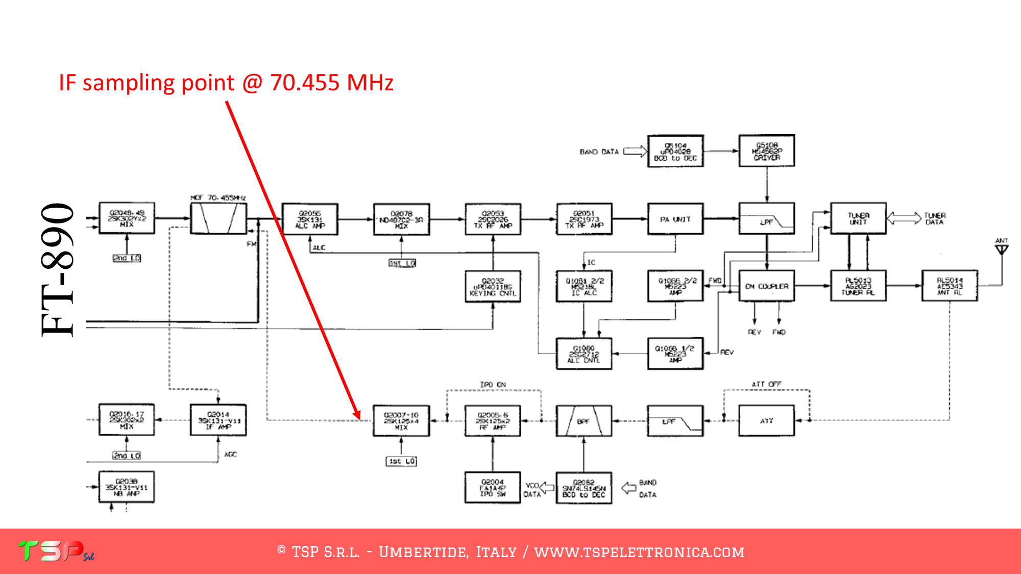
The operations to be carried out are very simple, it is sufficient to obtain from its wiring diagram the information on the points where the IF signal has to be taken. This radio uses several mixers and we are interested in the first IF frequency (this makes it easier to operate the panadapter). The IF frequency chosen is 70.455 MHz and our SDR panadapter will be tuned to this. The following image shows the block diagram of the radio and where to get the IF signal.
The following image shows the portions of the schematic diagram of the IF UNIT where we can see the exact points where to sample the IF signal and the power supply.
We now proceed to identify the exact points on the printed circuit board where to take the IF signal to be sent to the IFace. The following images show the sampling point for the IF signal and for the power supply for the buffer interface.
The use of PTT signal is not required because RX and TX signals are separated.
In order to buy an IFace use the buttons below.
ATTENTION: Though installing the IFace is not difficult, you do this at your own risk. TSP S.r.l. is not responsible for any damage, unwanted side-effects or whatever.
For more information, do not hesitate to write to us using the form below. Have fun!
Another very important testimonial has been sent to us by IZ4AQT Nicola and we can never say “thank you very much” enough. Here below we propose his full report.
https://youtu.be/W_3kcYuYjO8
This description is intended to be complementary to the article already published for the same apparatus modified with IFace v.1. The solution described here advantageously takes advantage of the small size that the IFace v.2 interface “without connectors” has; in particular, the extremely limited thickness of the SMD construction made it possible to choose a location inside the “shielded box” of the RF Unit. Having used a rather rigid shielded cable (RG 316 / U), and the sampling point of the IF signal being particularly hidden, particular care had to be taken in the path and execution of the solderings. Primary objective: we must have curves of the coaxial cable sufficiently wide so as not to create excessive stress on the welding points. The photos below show the sequence of the implementation steps of the change.
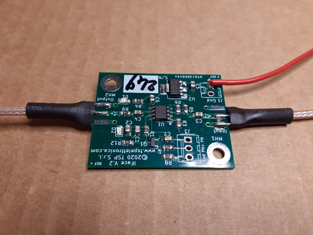
Preparing the IFace for installation
In this phase the coaxial input and output signal cables and the power supply cable (in red) have been soldered to the board.
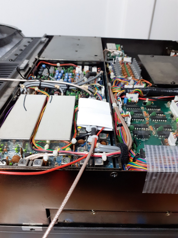
Check the overall dimensions in the final position
In this phase it was checked that the IFace v.2, suitably sandwiched between two insulating layers of plasticized cardboard, could easily find its place inside the RF Unit compartment.
Welding of the IF pickup cable
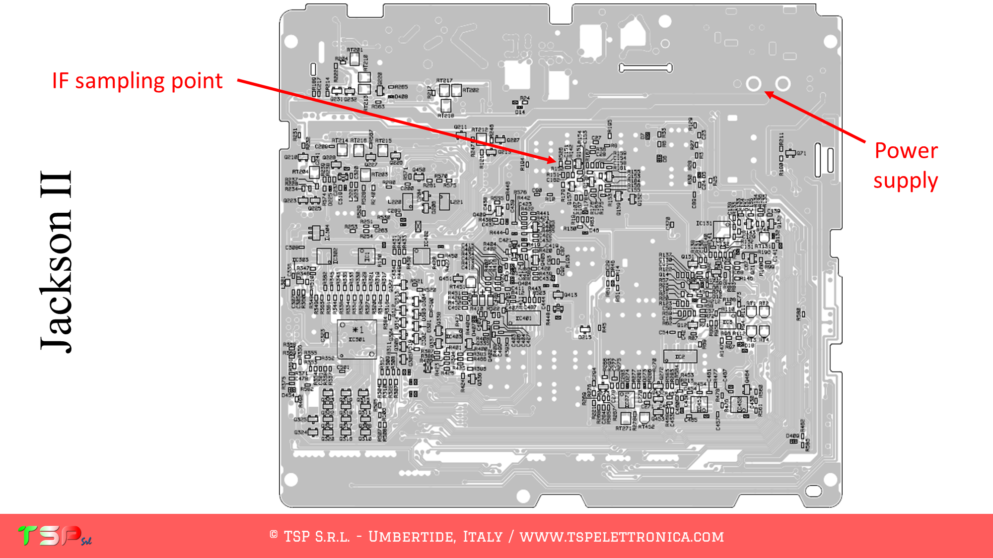
To facilitate soldering of the IF pickup cable, the RF Unit board has been removed from its housing so that the contacts on its underside can be easily accessed. The image below shows the solder side of this board.
The points where to carry out the soldering to take the IF signal and the power supply are shown in the following image. It should be noted that the welding, for convenience, will then be carried out on the lower side.
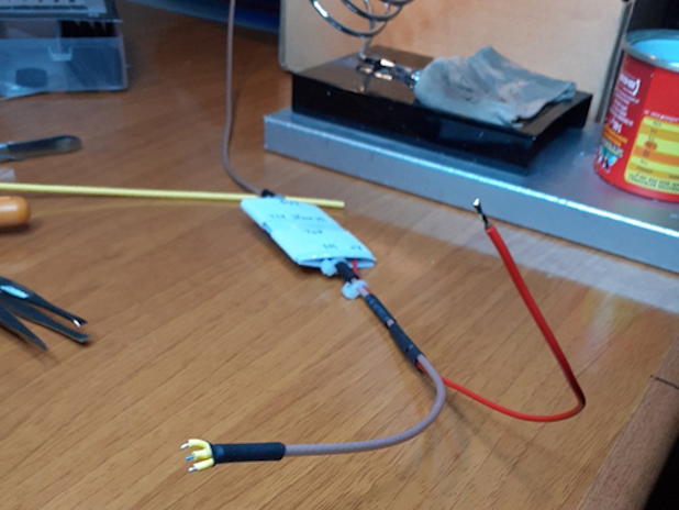
Uscita del segnale IF
In this image you can see the Teflon coaxial cable (RG 316 / U) for the output of the IF signal.
This needs to be brought up to the rear panel of the radio.
Before arriving at the output connector, an RF choke was inserted in order to prevent any propagation of unwanted signals.
This was made with two cylindrical ferrites as can be easily verified from the following images.
The choke was then suitably protected with heat shrink tubing (in green).
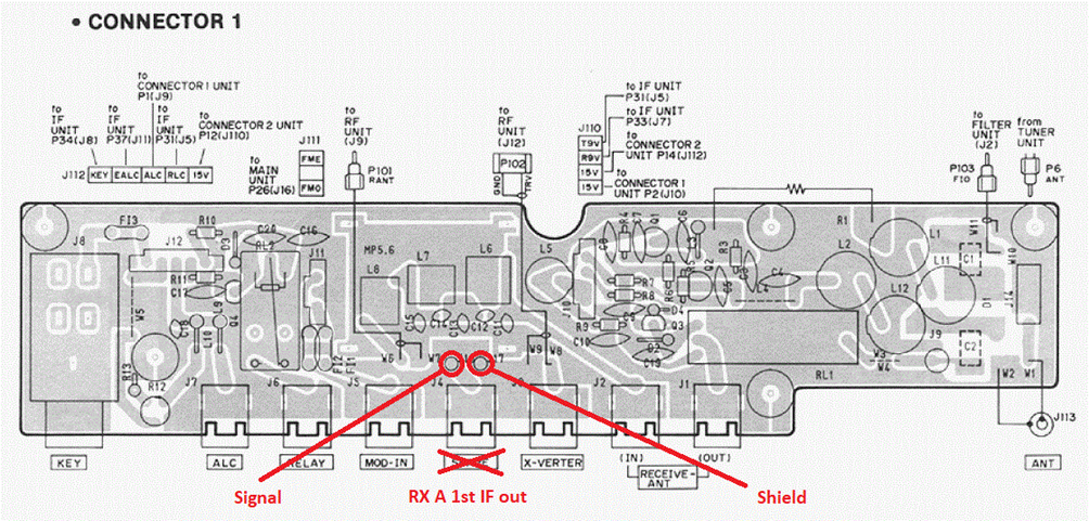
To bring the IF signal outside, it was decided to use the free “SPARE” connector on the rear panel of the radio.
This is accessible through special contacts on the printed circuit called “CONNECTOR 1”.
In order not to disassemble the “CONNECTOR 1” printed circuit board, it was decided not to solder the pins of the “SPARE” RCA connector and the end of the IF output cable from IFace v.2 was terminated with two golden female pins recovered from a military connector VEAM AMPHENOL.
At this point the work is finished and from the rear of the radio the IF signal is conveniently available and ready to be sent to the external SDR receiver (in the photo it is visible in blue).
Again a big thank you to IZ4AQT Nicola for this beautiful work of documentation of his installation.
For more information on our IFace buffer interface click here.
To find out about all the radios on which the card can be installed click here.
We remind you that to buy the IFace you can use one of the following buttons.
ATTENTION: Although the installation of IFace 2 is not difficult, it is done at your own risk. TSP S.r.l. is not responsible for any damage, unwanted side effects or anything else.
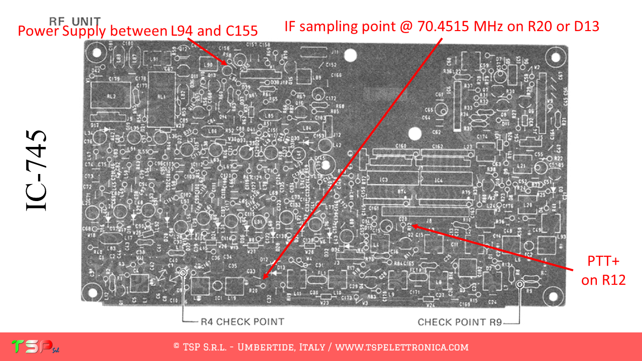
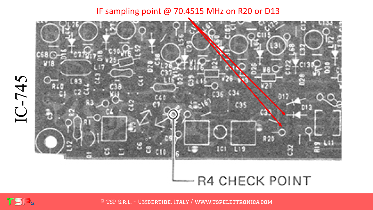
The operations to be carried out are very simple, it is sufficient to obtain from its wiring diagram the information on the points where the IF signal has to be taken. This radio uses several mixers and we are interested in the first IF frequency (this makes it easier to operate the panadapter). The IF frequency chosen is 70.4515 MHz and our SDR panadapter will be tuned to this. The following image shows the block diagram of the radio and where to get the IF signal.
The following image shows the portions of the schematic diagram of the IF UNIT where we can see the exact points where to sample the IF signal, the PTT+ and the power supply.
We now proceed to identify the exact points on the printed circuit board where to take the IF signal to be sent to the IFace. The following images show the sampling point for the IF signal and for the power supply for the buffer interface.
The use of PTT signal is required because RX and TX signals are not completely separated.
In order to buy an IFace use the buttons below.
ATTENTION: Though installing the IFace is not difficult, you do this at your own risk. TSP S.r.l. is not responsible for any damage, unwanted side-effects or whatever.
For more information, do not hesitate to write to us using the form below. Have fun!
This website uses cookies to improve your experience. We'll assume you're ok with this, but you can opt-out if you wish.AcceptRead More
Privacy & Cookies Policy
Privacy Overview
This website uses cookies to improve your experience while you navigate through the website. Out of these, the cookies that are categorized as necessary are stored on your browser as they are essential for the working of basic functionalities of the website. We also use third-party cookies that help us analyze and understand how you use this website. These cookies will be stored in your browser only with your consent. You also have the option to opt-out of these cookies. But opting out of some of these cookies may affect your browsing experience.
Necessary cookies are absolutely essential for the website to function properly. This category only includes cookies that ensures basic functionalities and security features of the website. These cookies do not store any personal information.
Any cookies that may not be particularly necessary for the website to function and is used specifically to collect user personal data via analytics, ads, other embedded contents are termed as non-necessary cookies. It is mandatory to procure user consent prior to running these cookies on your website.
NEWS July 18, 2024 A Telegram group is now available through which you can interact to get faster responses from other customers or, if necessary, from TSP Srl.
Sign up for free by clicking here: Telegram TSP Customers.
Please limit the use of contact forms to send generic requests, they have low reading priority because they are often used to send spam.
NOVITA' 18 Luglio 2024
E' da oggi disponibile un gruppo Telegram tramite il quale interagire per avere risposte più veloci da altri clienti o, in caso, da TSP Srl.
Iscrivetevi gratuitamente facendo click qui: Telegram Clienti TSP.
Per favore limitare l'utilizzo dei form di contatto per inviare richieste generiche, hanno bassa priorità di lettura perché spesso usati per inviare spam.