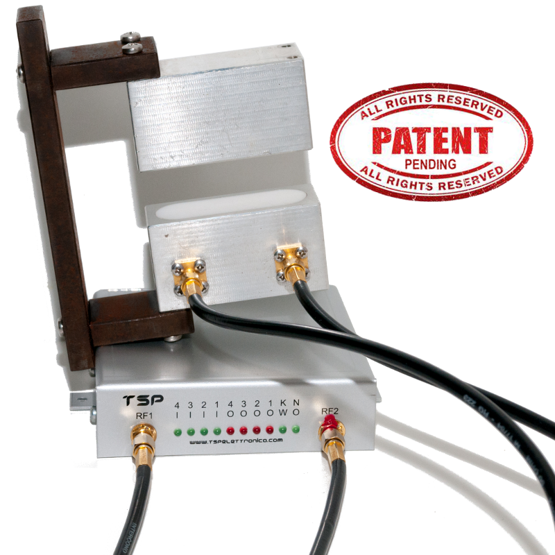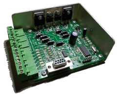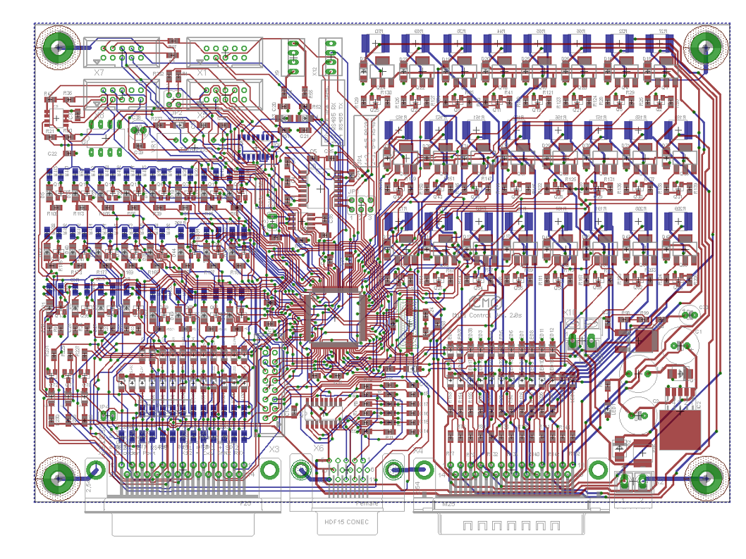
This electronic board, now in its third generation, controls the power supply of two electromagnetically operated brake/clutch units.
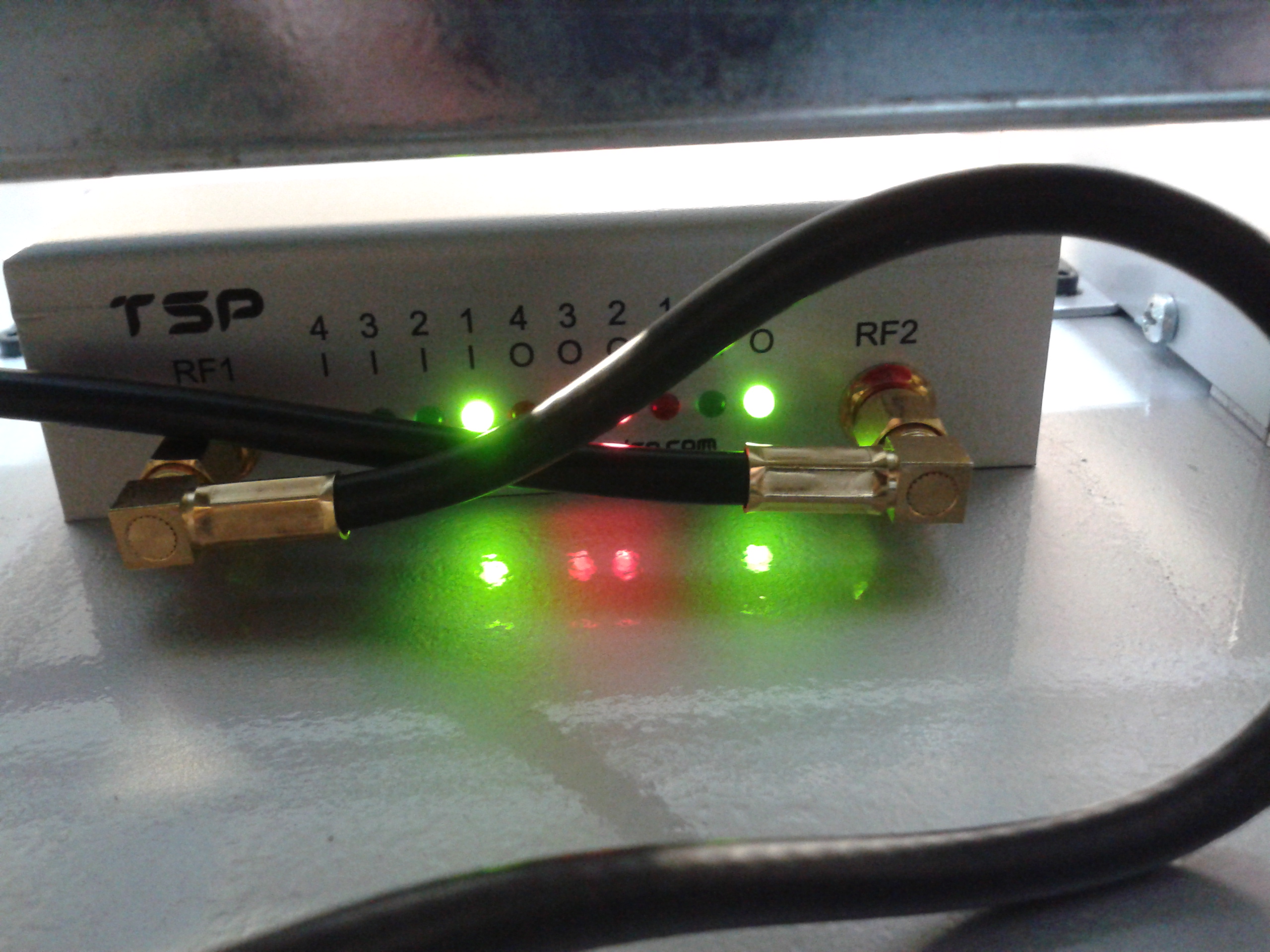
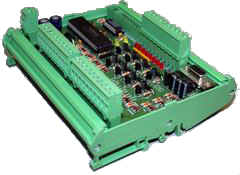
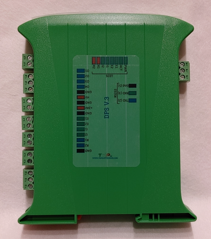
Compared to the previous version, it maintains its functionality but has improved in power management and in terms of board layout. The container has also been changed, now equipped with a transparent front window from which the status LEDs can be seen.
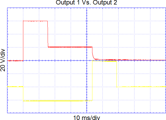
It is capable of continuously powering devices with a maximum absorption of 2 A @ 24 Vdc and, for a quicker response of the mechanical system, it provides a programmable timed boost, via the RS232 serial port, from 1 to 255 ms and up to 48 Vdc.
A 16-bit microcontroller governs all functions. In this way, it is possible to implement control functions that are difficult to obtain with simple analog circuits or circuits based on logic networks.
The two channels dedicated to driving the brake and clutch are managed independently, i.e. the times of the boosts can also be set for different durations. They can also be used to drive only two clutches or two brakes, one for each channel, it is not binding to connect both electromechanical parts to both channels.
Switching takes place by piloting a suitable digital input: if in the LOW state, for example, the brake is activated, if in the HIGH state, the clutch (the outputs can still be swapped).
A further input is used as an ENABLE signal: connected, for example, to the machine emergency management line, it allows disabling all the outputs, i.e. the power supply to each channel is cut off.
In addition to the two pairs of outputs for controlling the brake/clutch units, there are two other PNP outputs (max 50 mA @ 24 Vdc) used to indicate the so-called READY signal, one per channel.
The system can also operate at 12 Vdc.
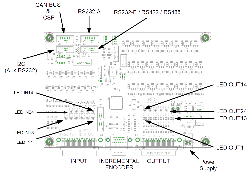
Power supply:
- one input for the voltage of 12/24 Vdc ± 10% for the control logic and brake / clutch in steady state;
- one input for the voltage of 24 ÷ 48 Vdc for the overvoltage of the brake / clutch unit.
4 PNP inputs:
- 2 x enable signal from the machine controller;
- 2 x digital input to change the state of the output (e.g. LOW = brake, HIGH = clutch).
6 PNP outputs:
- 2 x 24 VDC / 2 A brake power supply (up to 48 VDC) with programmable duration;
- 2 x 24 VDC / 2 A clutch power supply + supercharging (up to 48 VDC) with programmable duration;
- 2 x READY signal.
RS232 serial port: (115200,8,N,1) this is mainly used to change the setup of the board, i.e. the timing of the overvoltages.
Maximum switching frequency: this is mainly overvoltage time dependant.
Minimum command impulse duration: < 1 ms (typically 200 us).
Dimensions: the electronic board is housed in a DIN bar container with dimensions of 101 x 120mm x 22.5 mm.
It is possible to customize the firmware, if required.
For more information, please use the following form.