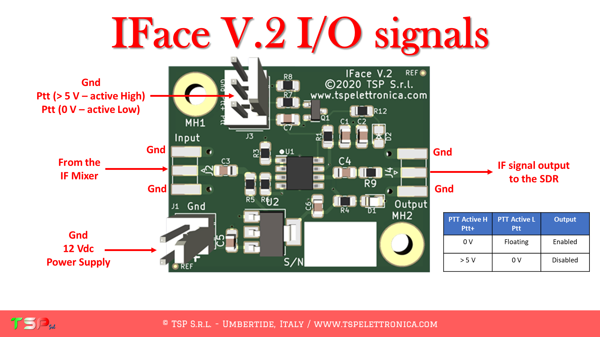
These are the instructions to install the IFace interface inside of the Ranger RCI-2970N2 in order to add an SDR panadapter to the radio. The installation is very easy.
After removing the cover, locate the main electronic board: the signal we are interested in are on this board. The SDR receiver will be tuned on 10.695 MHz.
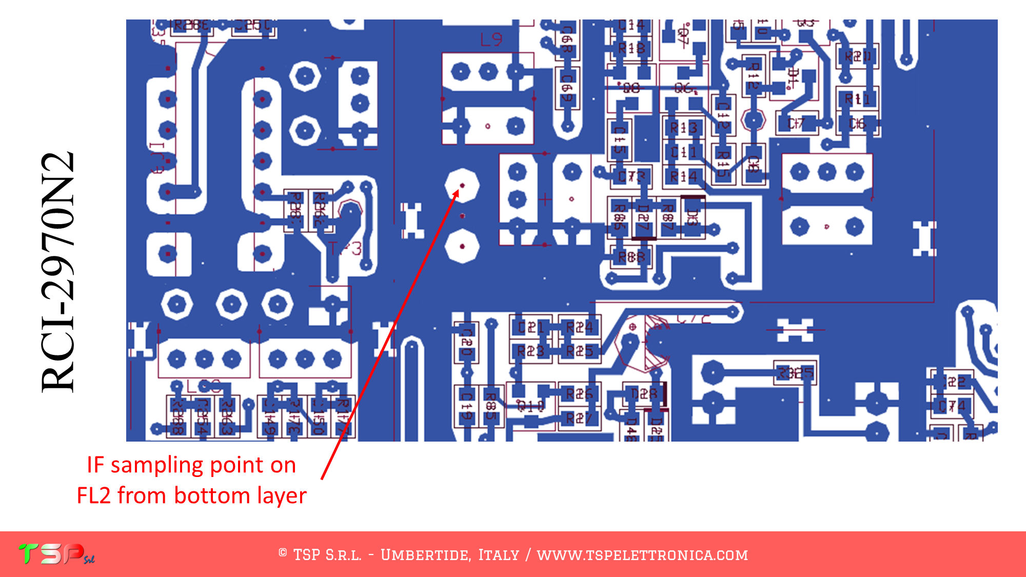
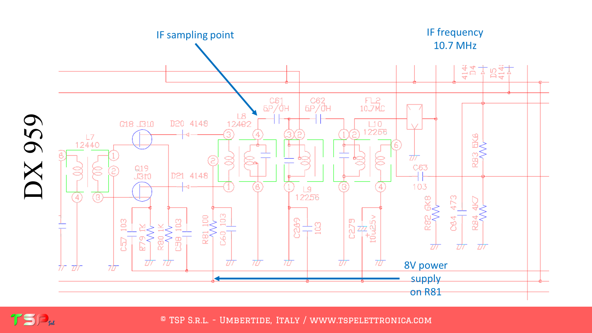
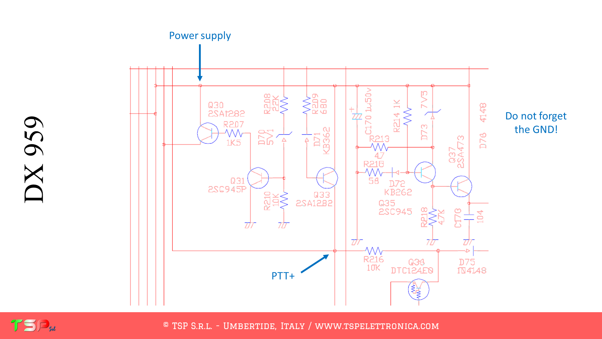
Refer to the following image of the wiring diagram to identify the points where you can weld the cables for the IF and the power supply. The PTT+ is not required, the signal paths for the RX and the TX are mostly separated.
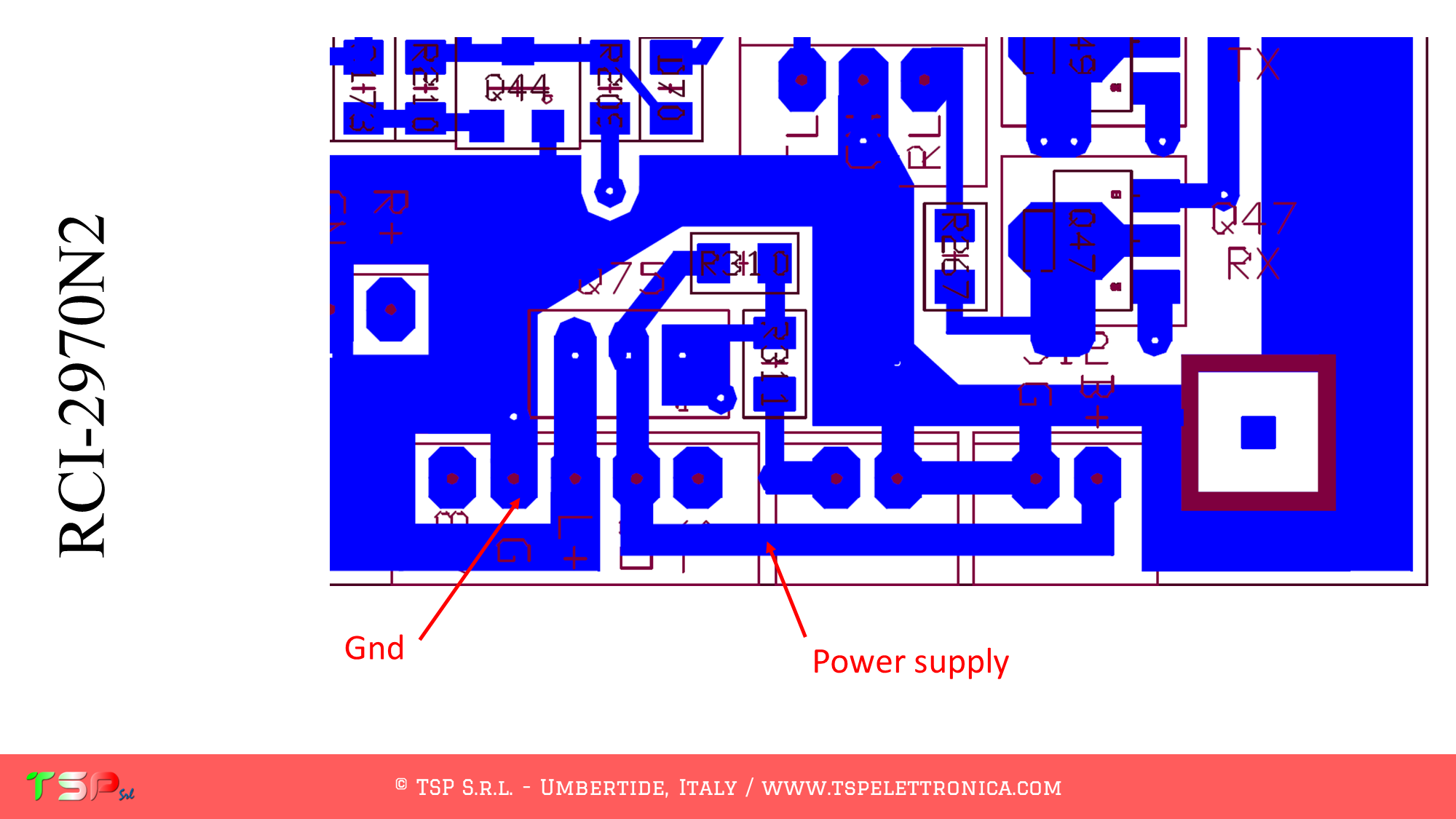
Refer to the following images to identify the points on the PCB where to solder the various connection cables between radio and IFace.
In order to buy an IFace please use the following buttons.
ATTENTION: Though installing the IFace is not difficult, you do this at your own risk. TSP S.r.l. is not responsible for any damage, unwanted side-effects or whatever.
For more information do not hesitate to write us. Have fun!
These are the instructions to install the IFace interface inside of the YAESU FT-747GX in order to add an SDR panadapter to the radio. The installation is very easy.
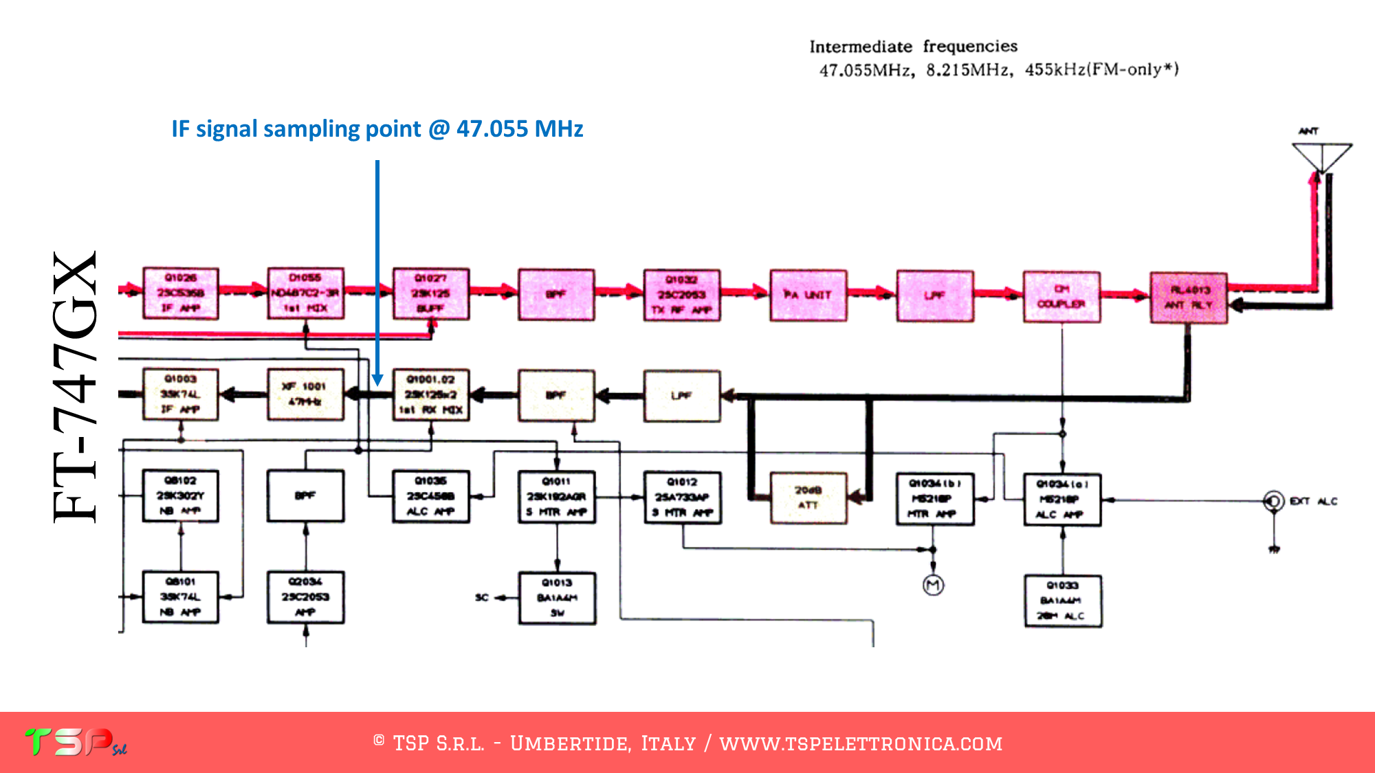
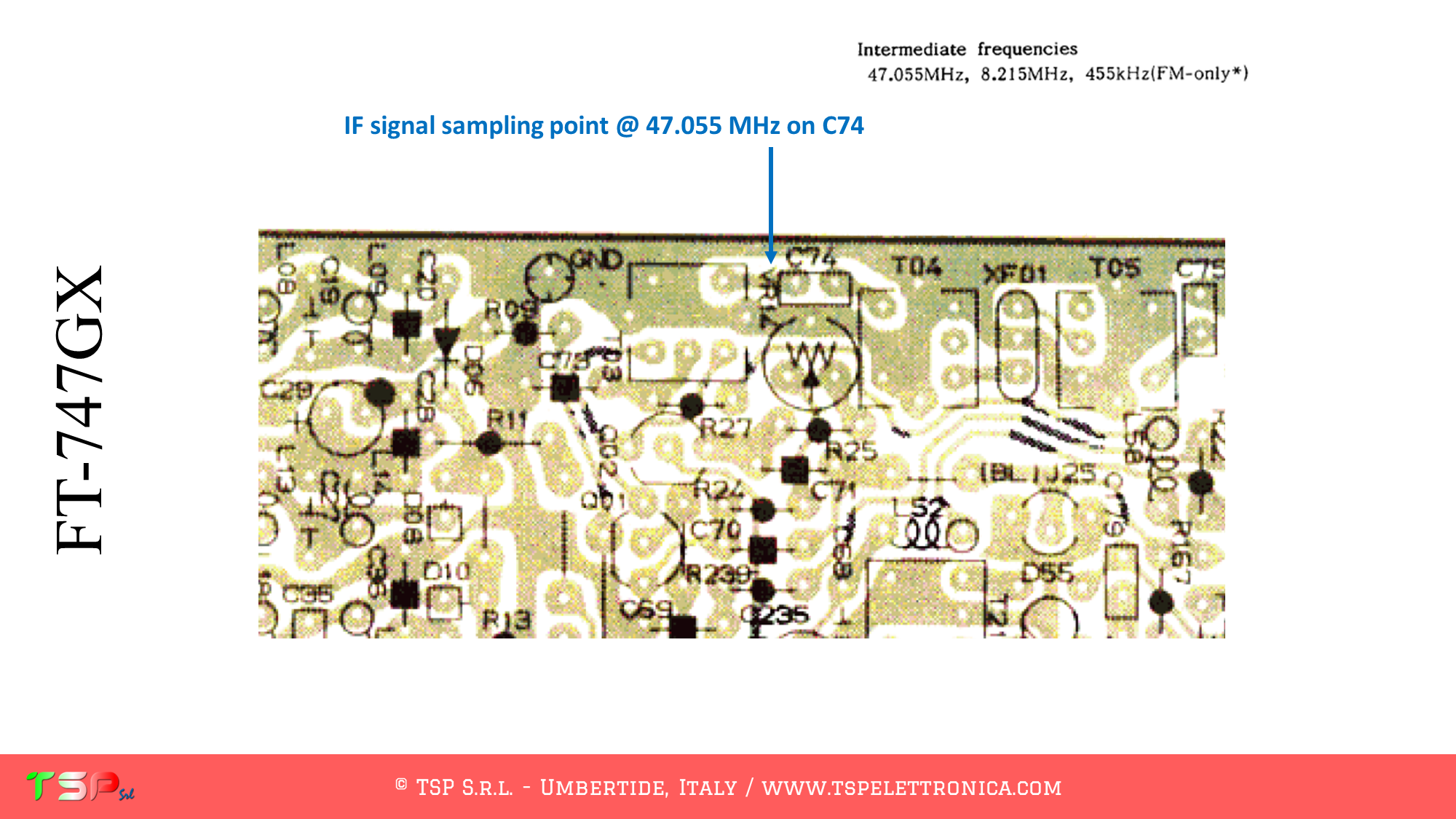
After removing the cover, locate the electronic board called “MAIN UNIT”: the signal we are interested in are on this board. The SDR receiver will be tuned on 47.055 MHz.
Refer to the following image of the wiring diagram to identify the points where you can weld the cables for the IF and the power supply. The PTT+ is not required, the signal paths for the RX and the TX are mostly separated.
Refer to the following images to identify the points on the PCB where to solder the various connection cables between radio and IFace.
In order to buy an IFace please use the following buttons.
ATTENTION: Though installing the IFace is not difficult, you do this at your own risk. TSP S.r.l. is not responsible for any damage, unwanted side-effects or whatever.
For more information do not hesitate to write us. Have fun!
These are the instructions to install the IFace interface inside of the YAESU FT-920 in order to add an SDR panadapter to the radio. The installation is very easy.
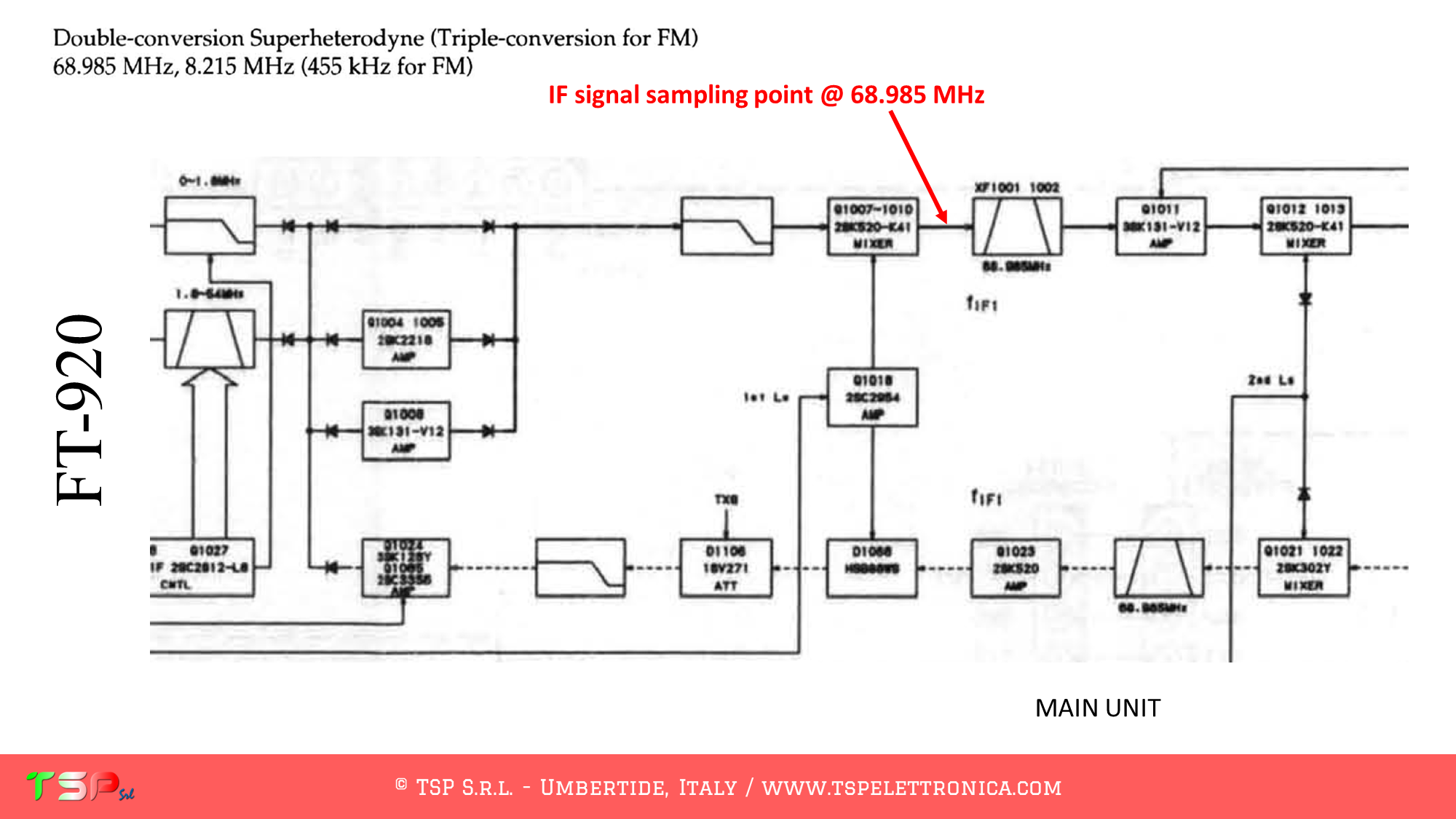
After removing the cover, locate the electronic board called “MAIN UNIT”: the signal we are interested in are on this board. The SDR receiver will be tuned on 68.985 MHz.
Refer to the following image of the wiring diagram to identify the points where you can weld the cables for the IF and the power supply. The PTT+ is not required, the signal paths for the RX and the TX are mostly separated.
Refer to the following image to identify the points on the PCB where to weld the various connecting wires.
In order to buy an IFace please use the following buttons.
ATTENTION: Though installing the IFace is not difficult, you do this at your own risk. TSP S.r.l. is not responsible for any damage, unwanted side-effects or whatever.
For more information do not hesitate to write us. Have fun!
In a previous article we presented how to install the IFace card inside the Kenwood TS-2000 in order to obtain the IF signal of all bands so that it can be sent to an external SDR. Now let’s see how to get the IF signal for the 23 cm band. Installation is very easy.
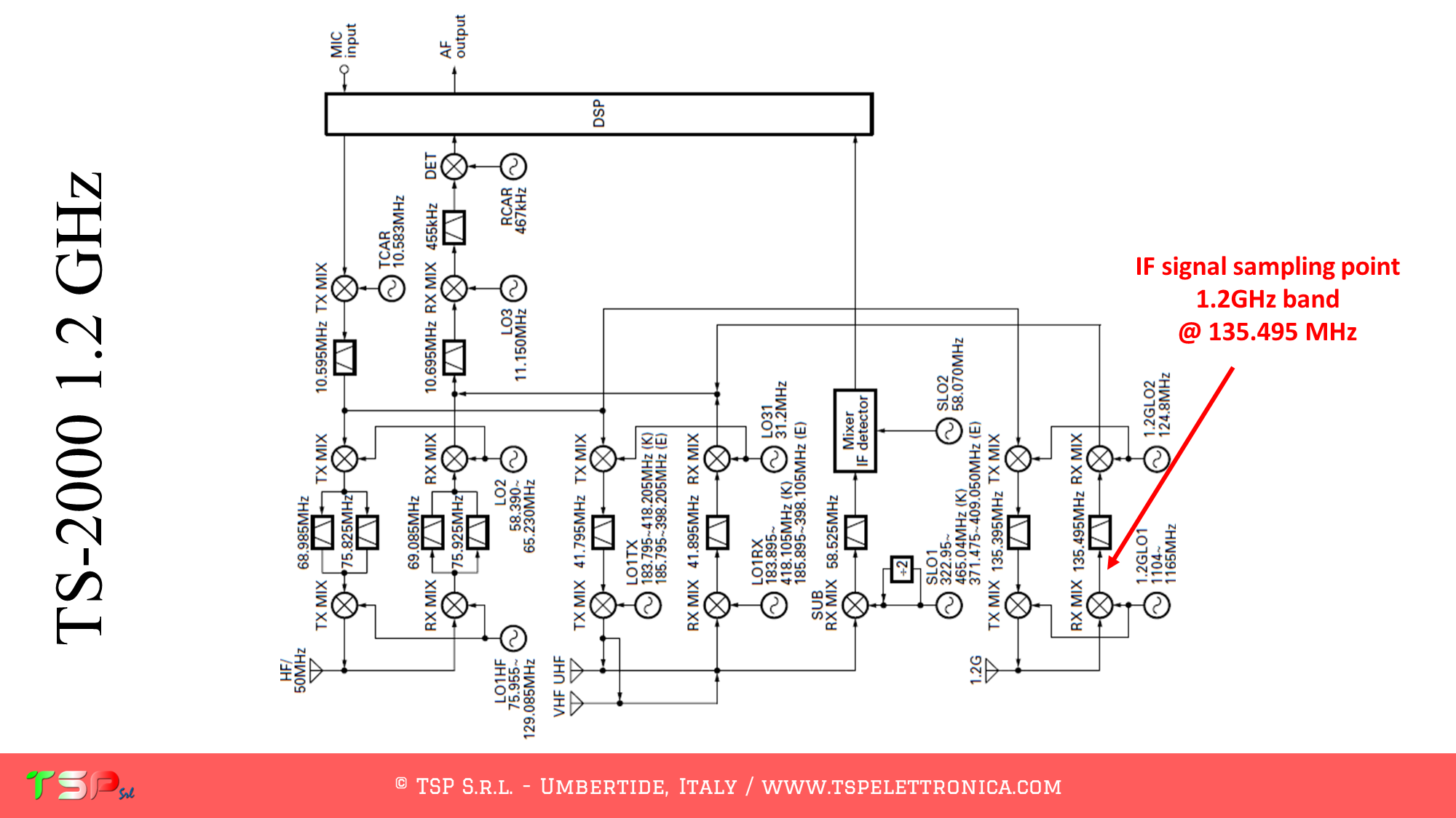
The TS-2000, like other radios, has a fairly complex configuration and uses different intermediate frequencies depending on the band on which you are operating. In any case, the one described here is the sequence of operations to be performed to obtain a bandwidth sufficient to provide a panoramic receiver around the IF frequency relative to the 23 cm band (1.2 GHz).
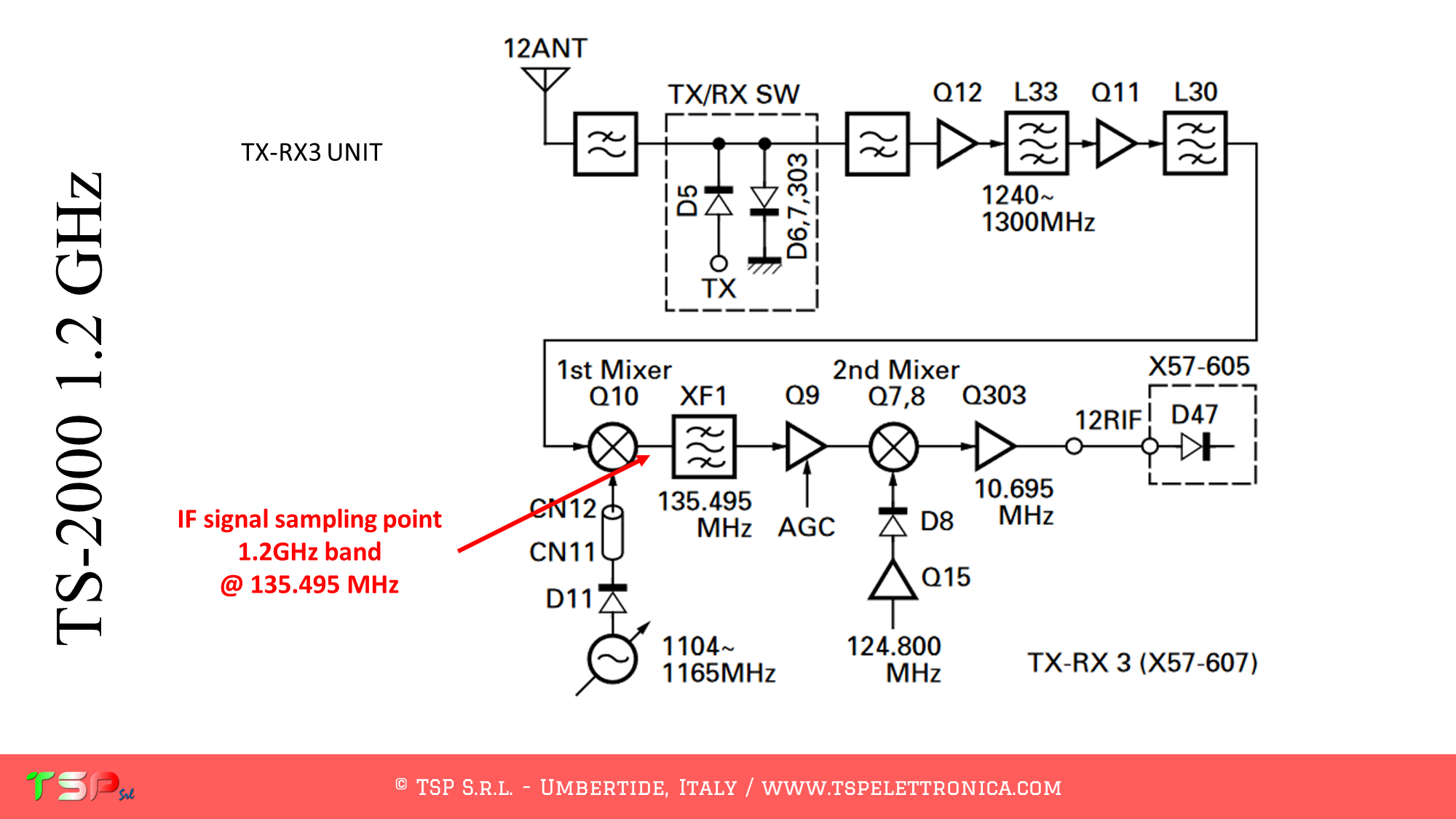
The point where to take the IF signal can be identified more precisely through the wiring diagram as shown in the following images. The electronic board of interest is the one called TX-RX3 and the signal can be taken from the CN8 connector.
The point where to take the IF signal on the TX-RX3 UNIT is indicated in the following image.
For the sake of completeness, a detail of the point where to take the power supply for the IFace card is also indicated.
PTT: This is not required for the TS-2000 as the reception circuit is muted during transmission.
You can purchase IFace 2 using one of the buttons below.
ATTENTION: Though installing the IFace is not difficult, you do this at your own risk. TSP S.r.l. is not responsible for any damage, unwanted side-effects or whatever.
For more information do not hesitate to write us. Have fun!
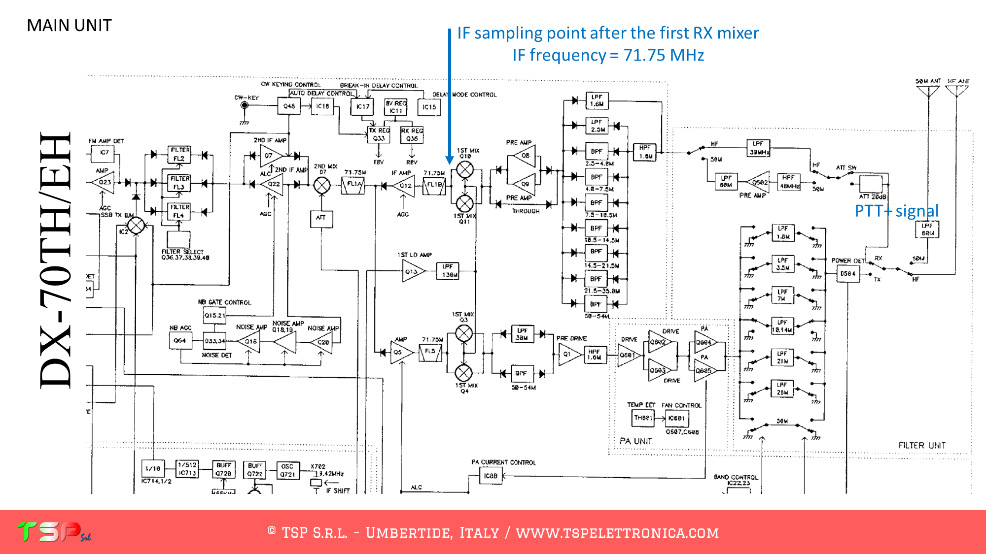
These are the instructions to install the IFace interface inside of the Alinco DX-70TH/EH in order to add an SDR panadapter to the radio. The installation is very easy.
After removing the cover, locate the electronic board called “MAIN UNIT”: the signal we are interested in are on this board. The SDR receiver will be tuned on 71.75 MHz.
Refer to the following images to identify in the wiring diagram the points where to weld the cables for the IF and the power supply (the PTT signal is not required because the RX and TX signal paths are separated).
Refer to the following image to identify the points on the PCB where to weld the various connecting cables.
In order to buy an IFace please use the following buttons.
ATTENTION: Though installing the IFace is not difficult, you do this at your own risk. TSP S.r.l. is not responsible for any damage, unwanted side-effects or whatever.
For more information do not hesitate to write us. Have fun!
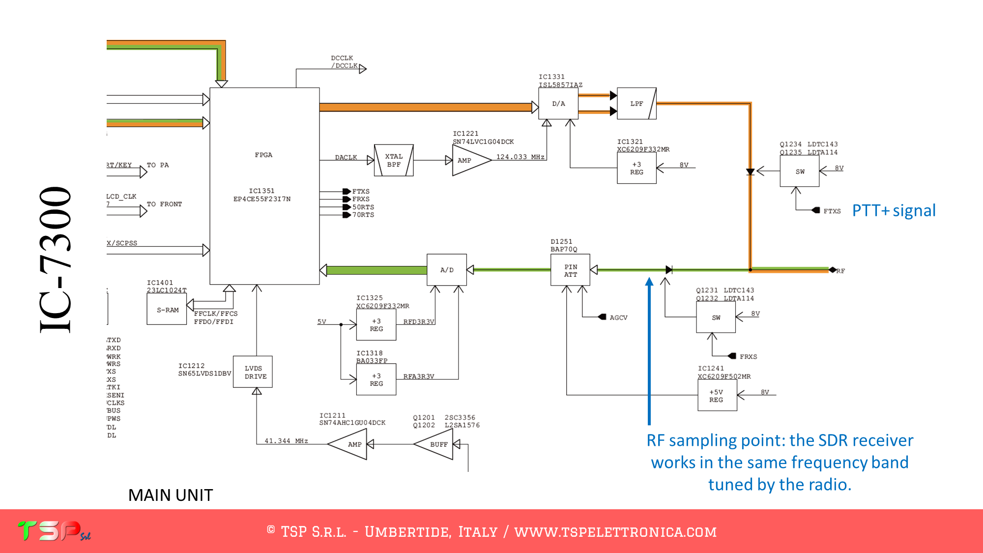
Let’s see how to install the IFace board inside the ICom IC-7300 in order to obtain an RF signal to be sent to an external SDR. In this way we will be able to have a second SDR receiver (and panadapter) that works in parallel to our radio and uses the same antenna. Obviously it will be active in reception only and on the same band in which the radio is operating as we will exploit the band filters of our RTX to improve the performance of our external receiver. Installation is very easy.
The IC-7300 has a direct sampling SDR architecture and therefore there are no mixers like in superheterodyne receivers. In this way we will go to sample the RF signal to be sent to our external SDR receiver upstream of the A / D converter of our Icom. By doing so we will have that the external receiver will work on the same band as the 7300, so during the transmission we will have to try to attenuate the transmitted signal as much as possible so as not to have a rather annoying RF return (it is possible, however, that a small part arrives equally to be received by the external SDR). For this purpose we will use the PTT+ input of the IFace board to disable the buffer.
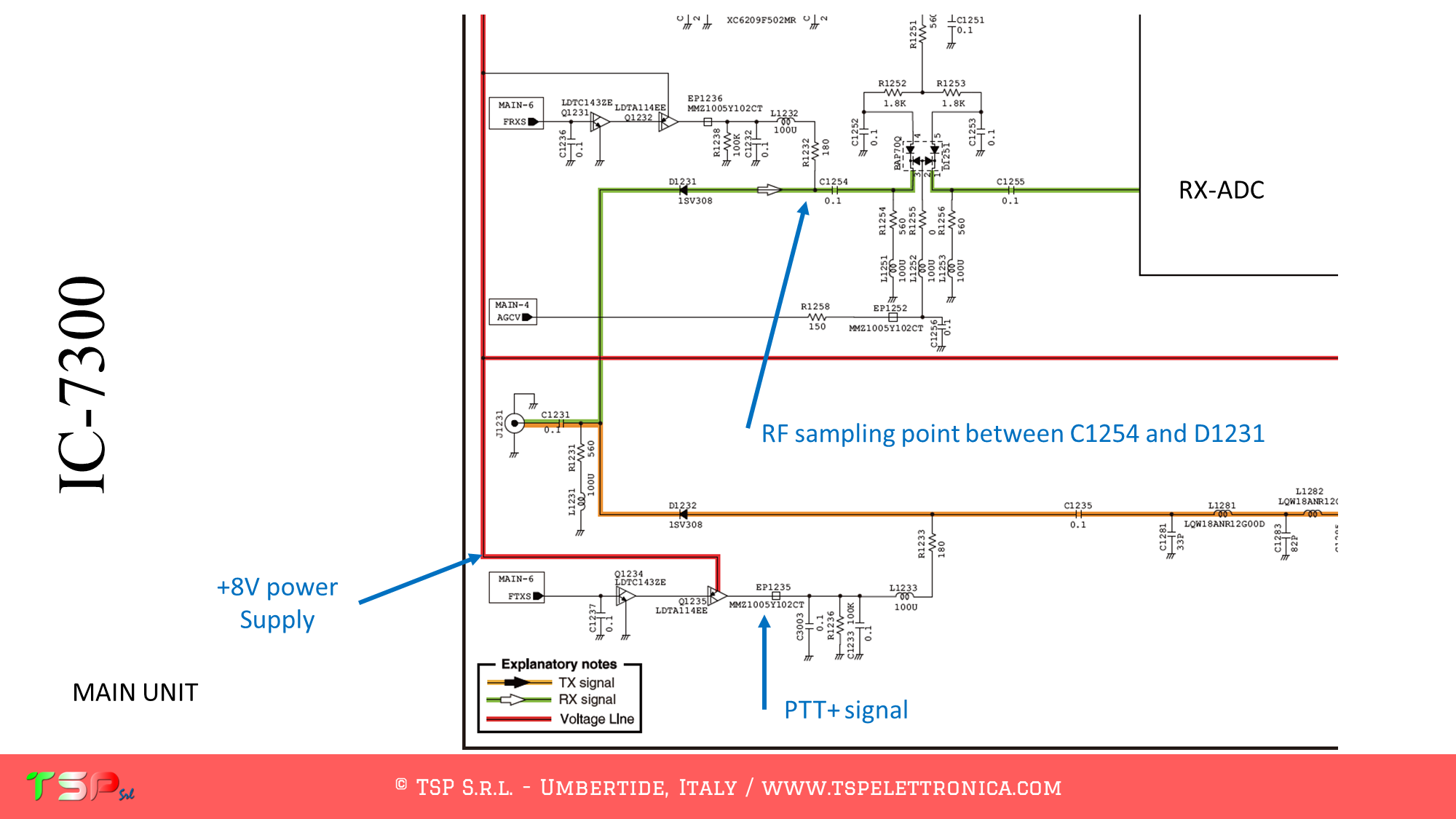
The signals to be sent to the IFace are shown in the following image: 8V power supply, PTT+ and RF signal.
The points on the PCB where to take the signals are shown below.
L’utilizzo del segnale relativo all’ingresso PTT+ per la scheda IFace è consigliato per ottenere un migliore isolamento del ricevitore esterno durante la trasmissione.
You can by IFace 2 simply making click on the buttons below.
ATTENTION: Though installing the IFace is not difficult, you do this at your own risk. TSP S.r.l. is not responsible for any damage, unwanted side-effects or whatever.
For more information do not hesitate to write us. Have fun!
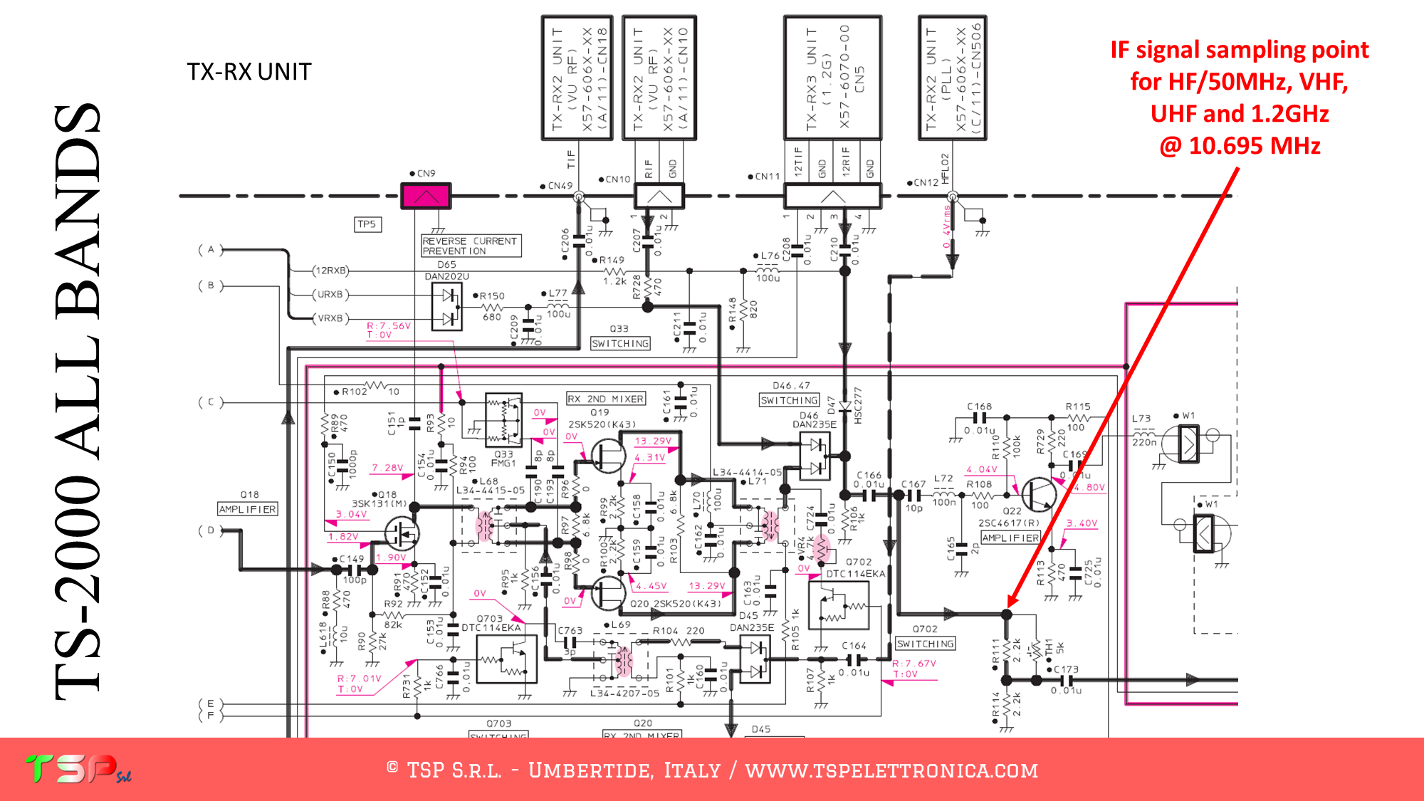
In two previous articles we have seen how to install the IFace card inside the Kenwood TS-2000 to obtain the IF signal of the HF and 50 MHz bands and of the VHF and UHF bands to be sent to an external SDR. Now let’s see how to get another single IF signal for all bands, including 23cm (1.2 GHz). Installation is very easy.
The result you can obtain is well shown in the following video.
The TS-2000, like other radios, has a fairly complex configuration and uses different intermediate frequencies depending on the band on which you are operating. There is the possibility of taking an IF signal at a single frequency (10,695 MHz) valid for all bands. This involves a reduction in the width of the displayable spectrum as the IF signal will have passed through some IF band filters. In any case, the one described here is the sequence of operations to be performed to obtain a bandwidth sufficient to create a panoramic receiver around the IF frequency relating to all the bands on which the radio can operate.
However, the displayable spectrum depends on the sampling frequency of the SDR receiver, not on IFace.
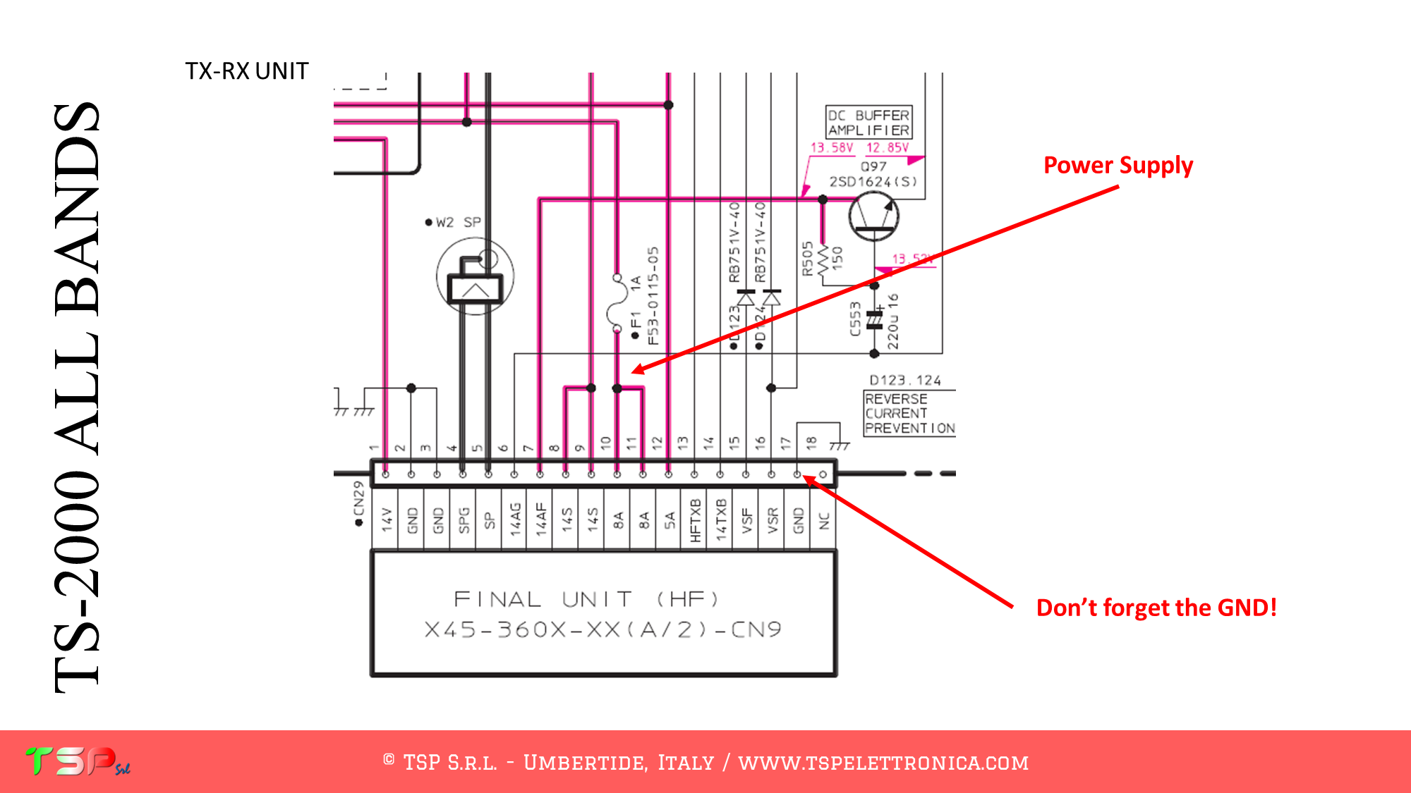
The point where to take the IF signal can be identified more precisely through the wiring diagram as shown in the following images. The electronic card of interest is the one called TX-RX UNIT and the signal can be taken among R111, C166 and C167.
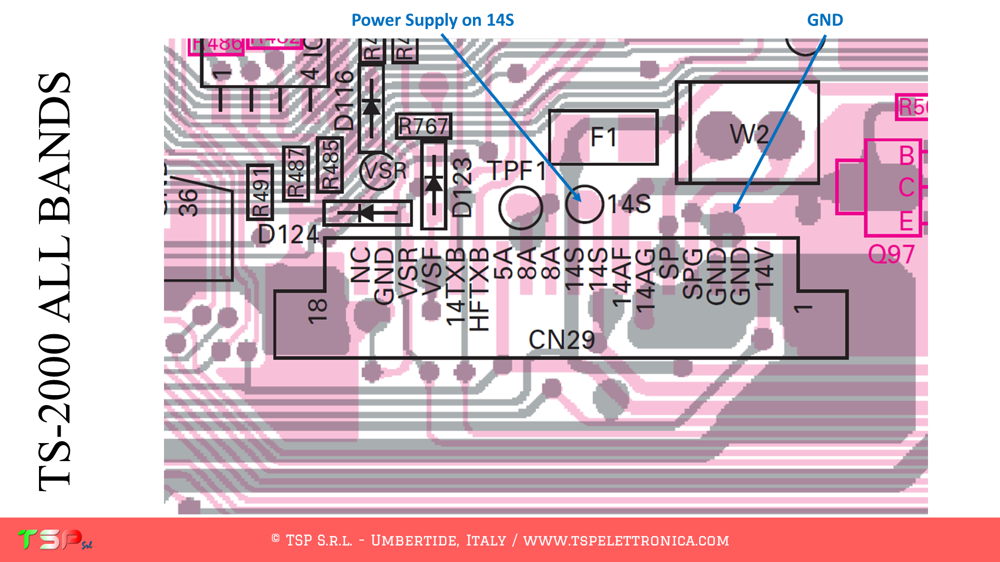
Now we have to look for where to take the power supply: power can be taken from the CN 29 connector, signal 14S or 8A.
The points on the PCB where to take the signals are shown below.
PTT: for the TS-2000 it is not required because the reception circuit is automatically muted during transmission.
You can by IFace 2 simply making click on the buttons below.
ATTENTION: Though installing the IFace is not difficult, you do this at your own risk. TSP S.r.l. is not responsible for any damage, unwanted side-effects or whatever.
For more information do not hesitate to write us. Have fun!
These are the instructions to install the IFace interface inside of the ICOM IC-736 / 738 in order to add an SDR panadapter to the radio. The installation is very easy.
After removing the cover, locate the electronic board called “MAIN UNIT”: the signal we are interested in are on this board. The SDR receiver will be tuned on 10.7 MHz.
Refer to the following image to identify in the wiring diagram the points where to weld the cables for the IF, the power supply and the PTT. Several points have been highlighted where you can take the power supply, choose the one that best suits the installation.
Refer to the following image to identify the points on the PCB where to weld the various connecting cables.
In order to buy an IFace please use the following buttons.
ATTENTION: Though installing the IFace is not difficult, you do this at your own risk. TSP S.r.l. is not responsible for any damage, unwanted side-effects or whatever.
For more information do not hesitate to write us. Have fun!
These are the instructions to install the IFace interface inside of the ICOM IC-736 / 738 in order to add an SDR panadapter to the radio. The installation is very easy.
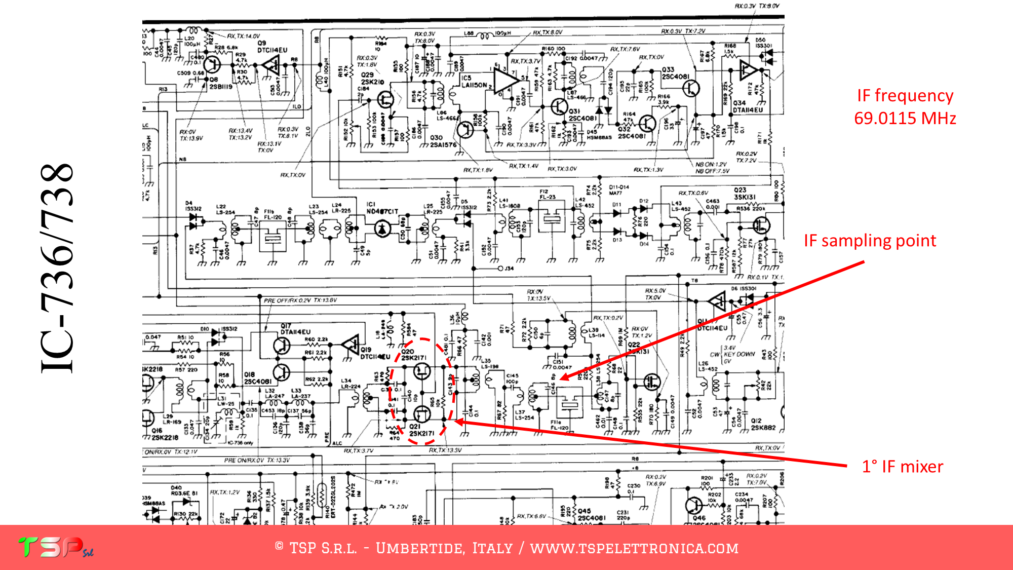
After removing the cover, locate the electronic board called “MAIN UNIT”: the signal we are interested in are on this board. The SDR receiver will be tuned on 69.0115 MHz.
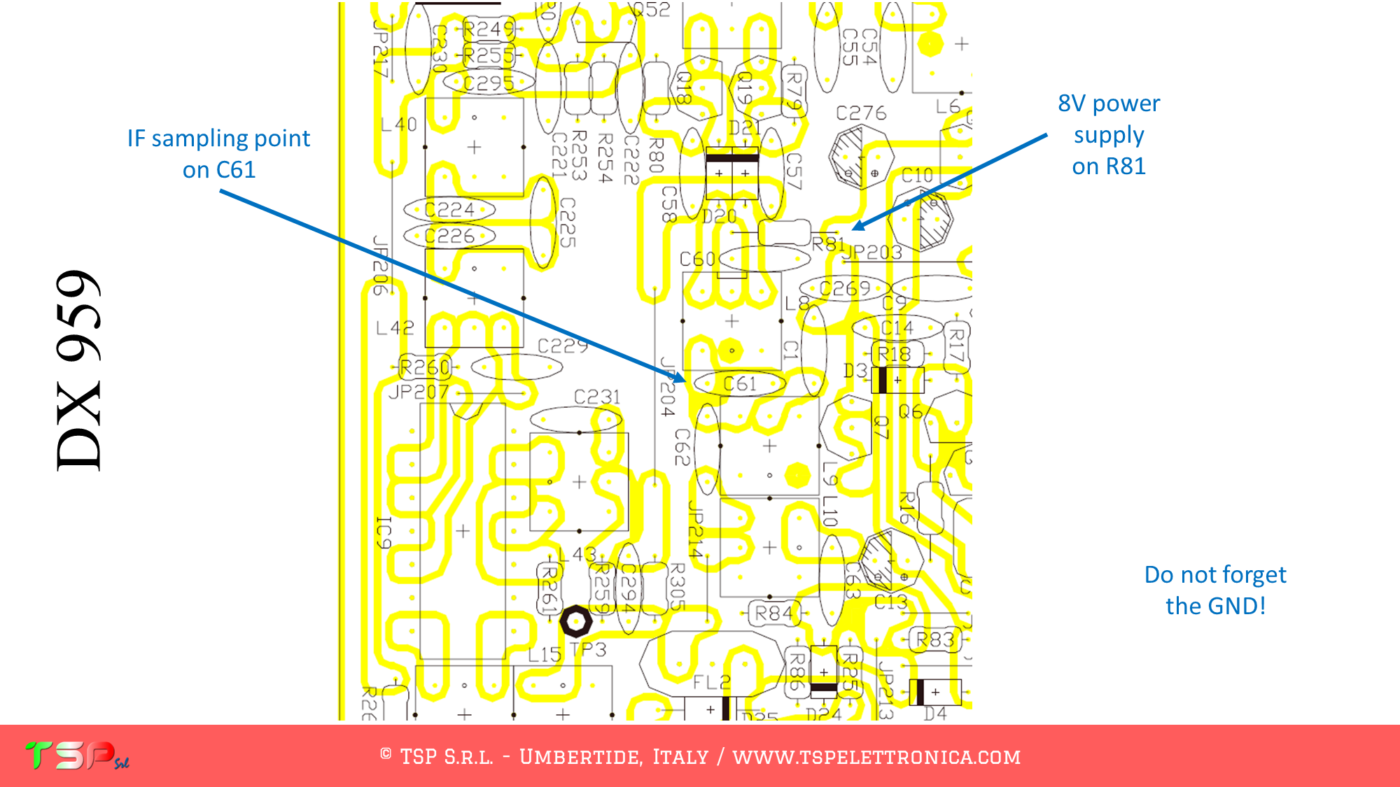
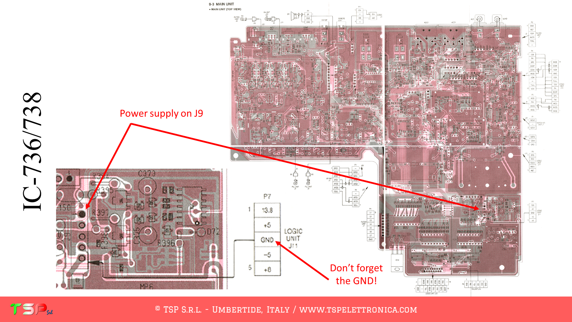
Refer to the following image of the wiring diagram to identify the points where you can weld the cables for the IF and the power supply. The PTT+ is not required, the signal paths for the RX and the TX are mostly separated.
Refer to the following image to identify the points on the PCB where to weld the various connecting cables.
In order to buy an IFace please use the following buttons.
ATTENTION: Though installing the IFace is not difficult, you do this at your own risk. TSP S.r.l. is not responsible for any damage, unwanted side-effects or whatever.
For more information do not hesitate to write us. Have fun!
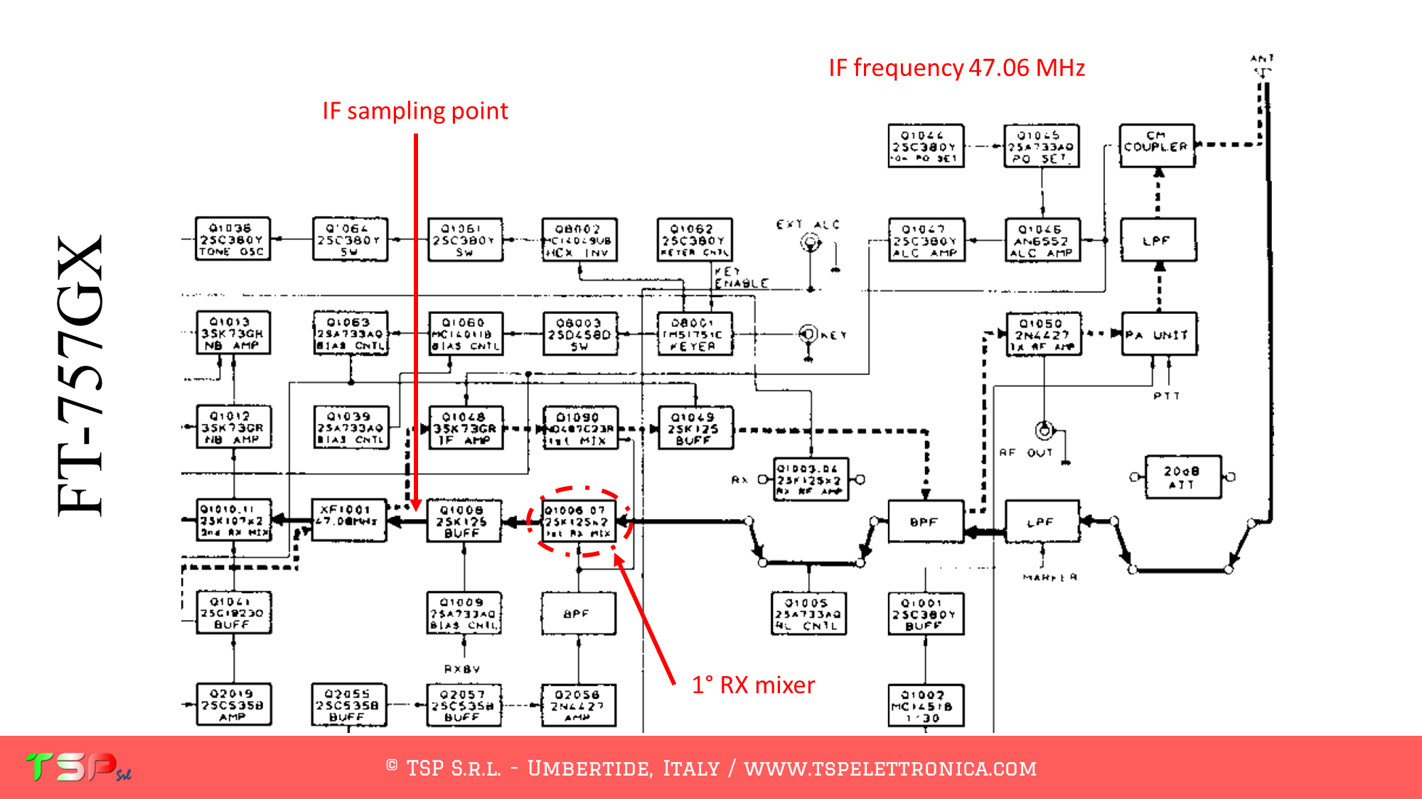
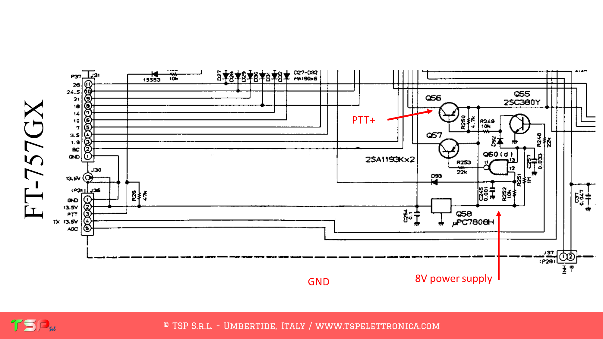
These are the instructions to install the IFace interface inside of the Yaesu FT-757GX in order to add an SDR panadapter to the radio. The installation is very easy.
After removing the cover, locate the electronic board called “RF UNIT”: the signal we are interested in are on this board.
Refer to the following image of the wiring diagram to identify the points where you can weld the cables for the IF and the power supply. The PTT+ is required, the signal paths for the RX and the TX are not completeley separated.
Refer to the following image to identify the points on the PCB where to weld the various connecting cables.
In order to buy an IFace please use the following buttons.
ATTENTION: Though installing the IFace is not difficult, you do this at your own risk. TSP S.r.l. is not responsible for any damage, unwanted side-effects or whatever.
For more information do not hesitate to write us. Have fun!
This website uses cookies to improve your experience. We'll assume you're ok with this, but you can opt-out if you wish.AcceptRead More
Privacy & Cookies Policy
Privacy Overview
This website uses cookies to improve your experience while you navigate through the website. Out of these, the cookies that are categorized as necessary are stored on your browser as they are essential for the working of basic functionalities of the website. We also use third-party cookies that help us analyze and understand how you use this website. These cookies will be stored in your browser only with your consent. You also have the option to opt-out of these cookies. But opting out of some of these cookies may affect your browsing experience.
Necessary cookies are absolutely essential for the website to function properly. This category only includes cookies that ensures basic functionalities and security features of the website. These cookies do not store any personal information.
Any cookies that may not be particularly necessary for the website to function and is used specifically to collect user personal data via analytics, ads, other embedded contents are termed as non-necessary cookies. It is mandatory to procure user consent prior to running these cookies on your website.
NEWS July 18, 2024 A Telegram group is now available through which you can interact to get faster responses from other customers or, if necessary, from TSP Srl.
Sign up for free by clicking here: Telegram TSP Customers.
Please limit the use of contact forms to send generic requests, they have low reading priority because they are often used to send spam.
NOVITA' 18 Luglio 2024
E' da oggi disponibile un gruppo Telegram tramite il quale interagire per avere risposte più veloci da altri clienti o, in caso, da TSP Srl.
Iscrivetevi gratuitamente facendo click qui: Telegram Clienti TSP.
Per favore limitare l'utilizzo dei form di contatto per inviare richieste generiche, hanno bassa priorità di lettura perché spesso usati per inviare spam.