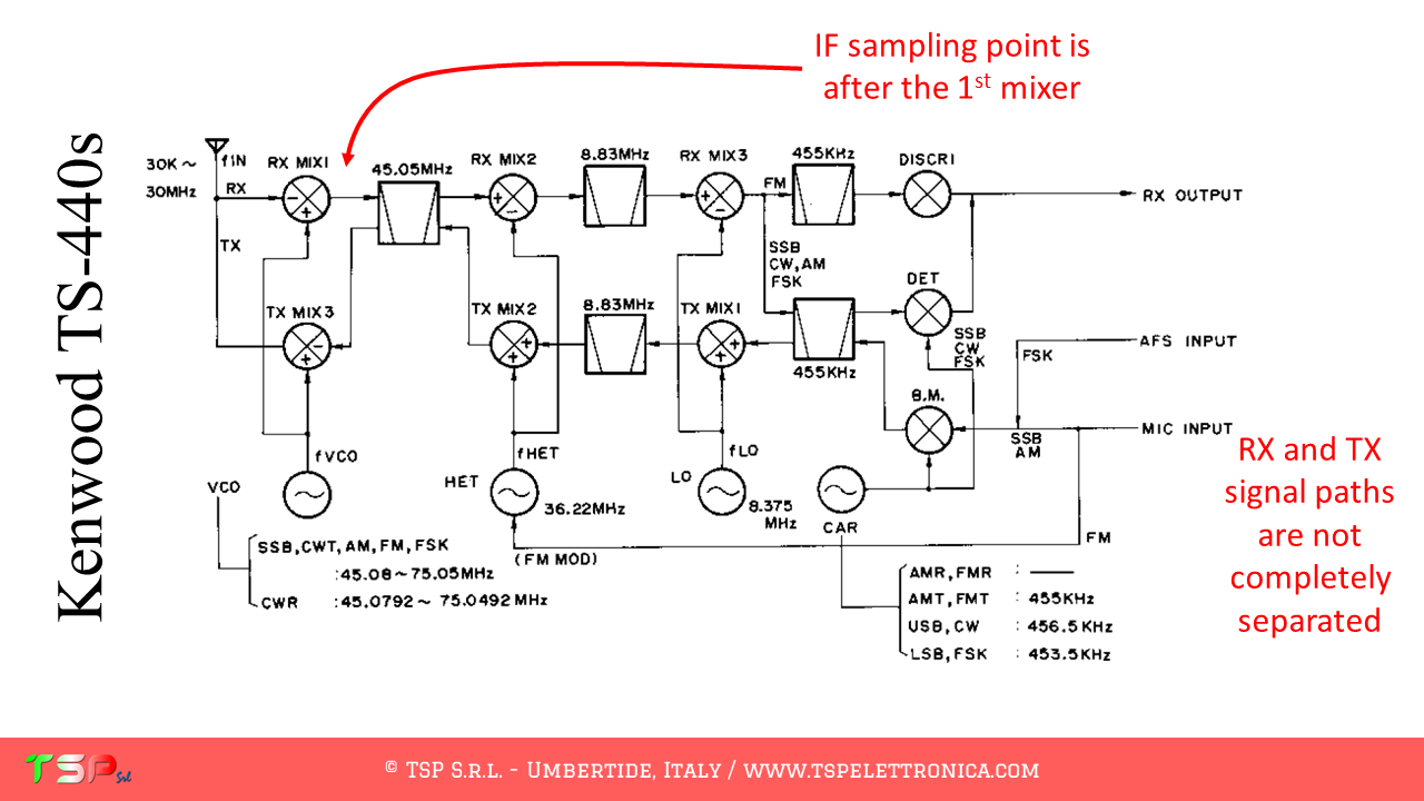
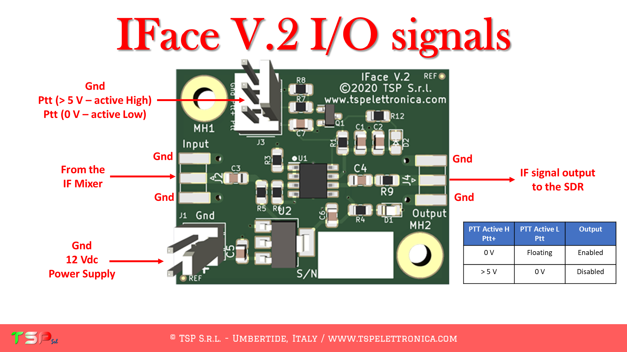
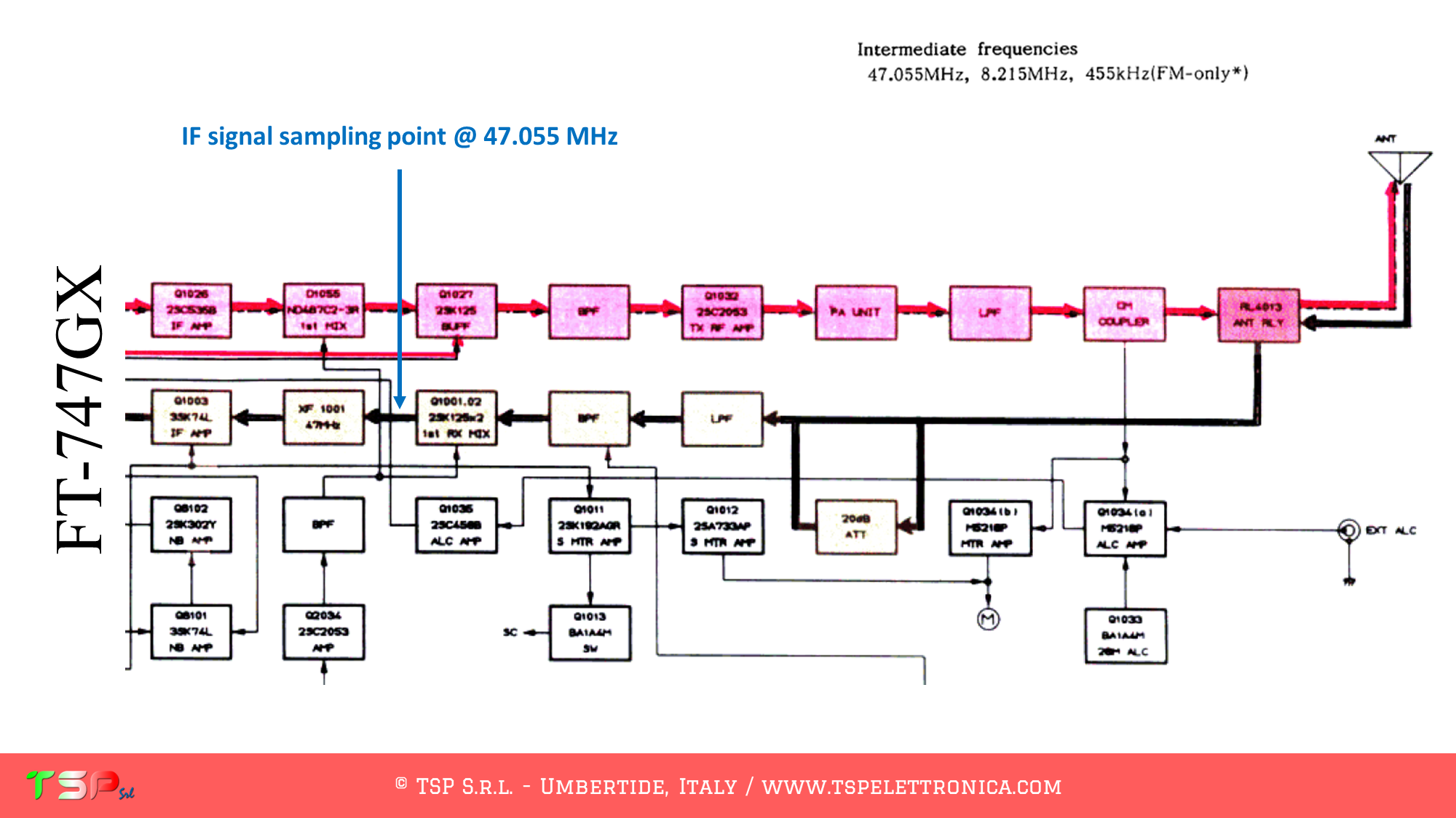
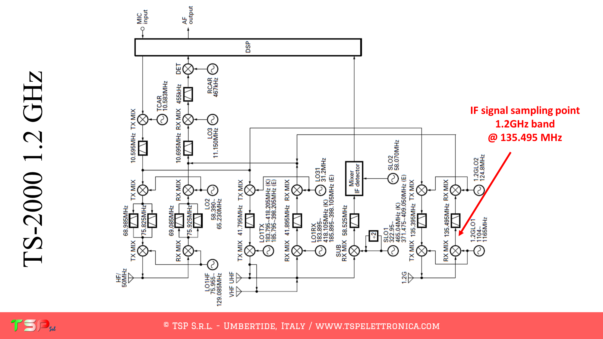
Below are the notes relating to the installation of the IFace interface inside the Yaesu FT-891 by IU7RAM Piero. In general, this work is done to be able to extract an IF signal from the radio reception chain so that it can be used to make an SDR panadapter and add an external SDR receiver. The application scheme is shown in the following image.
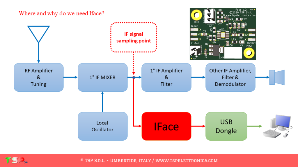
The signal to be sent to the external SDR receiver is taken immediately after the first receiving mixer and the frequency to which it will be tuned will be 69.450 MHz.
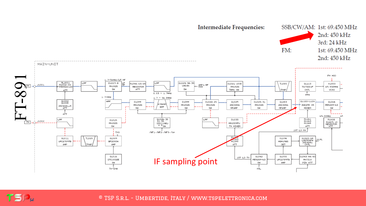
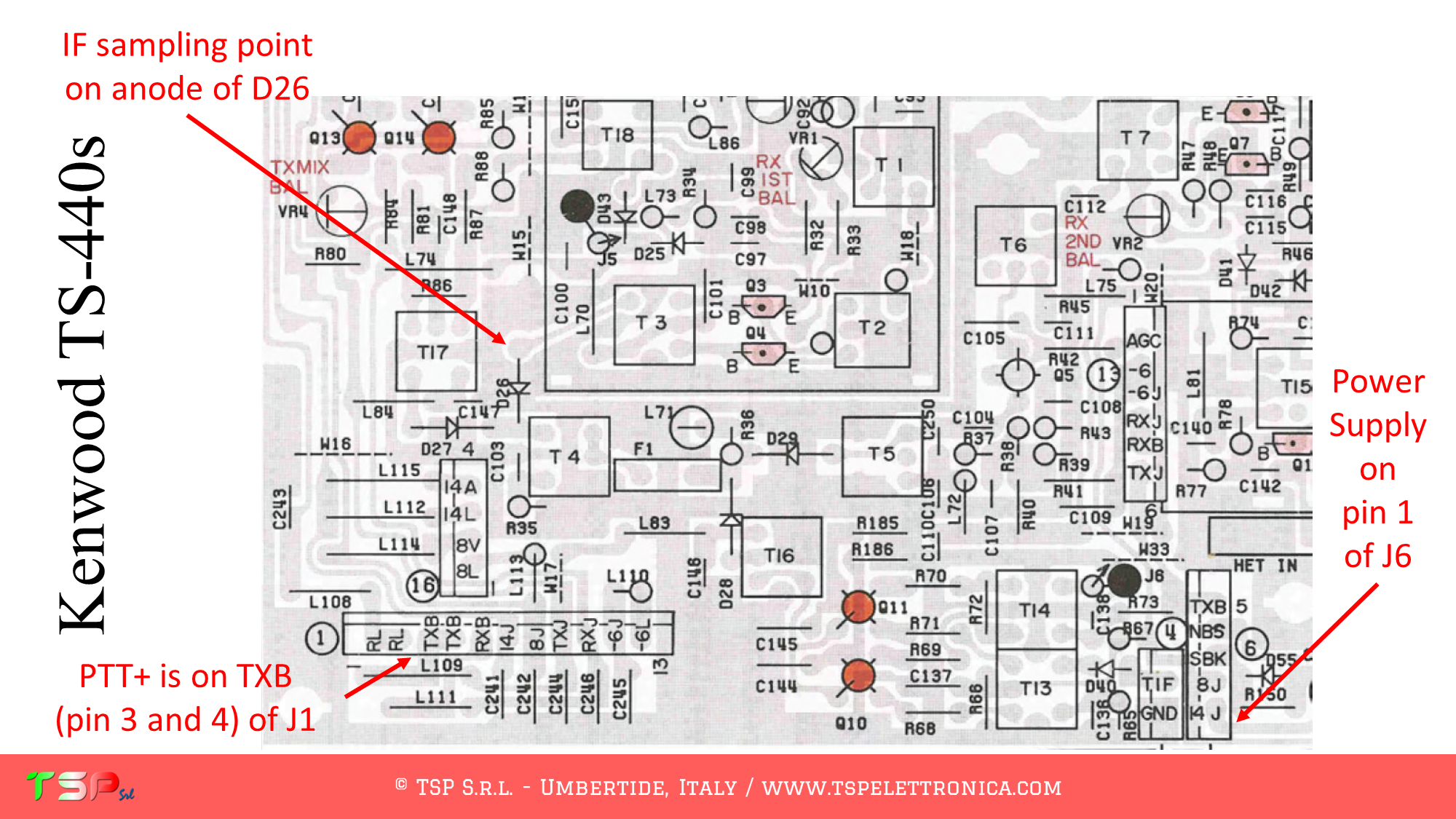
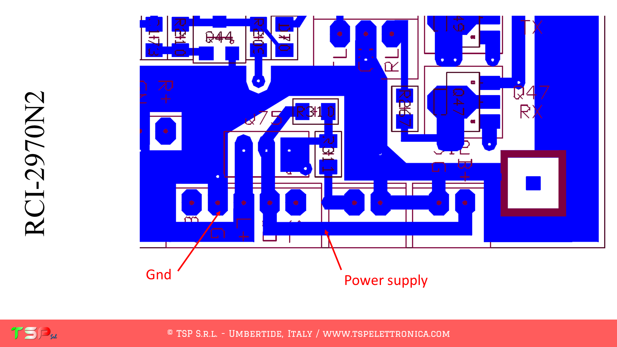
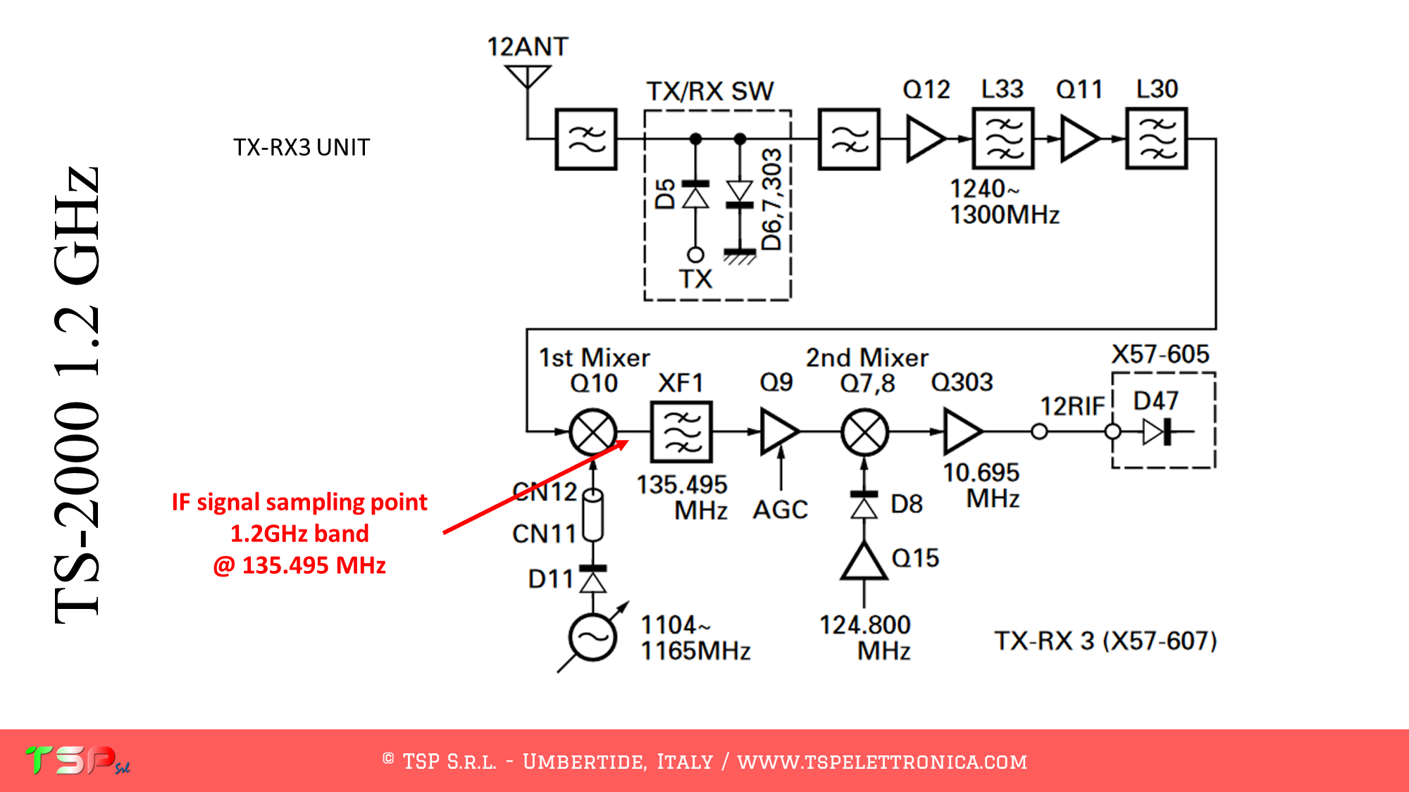
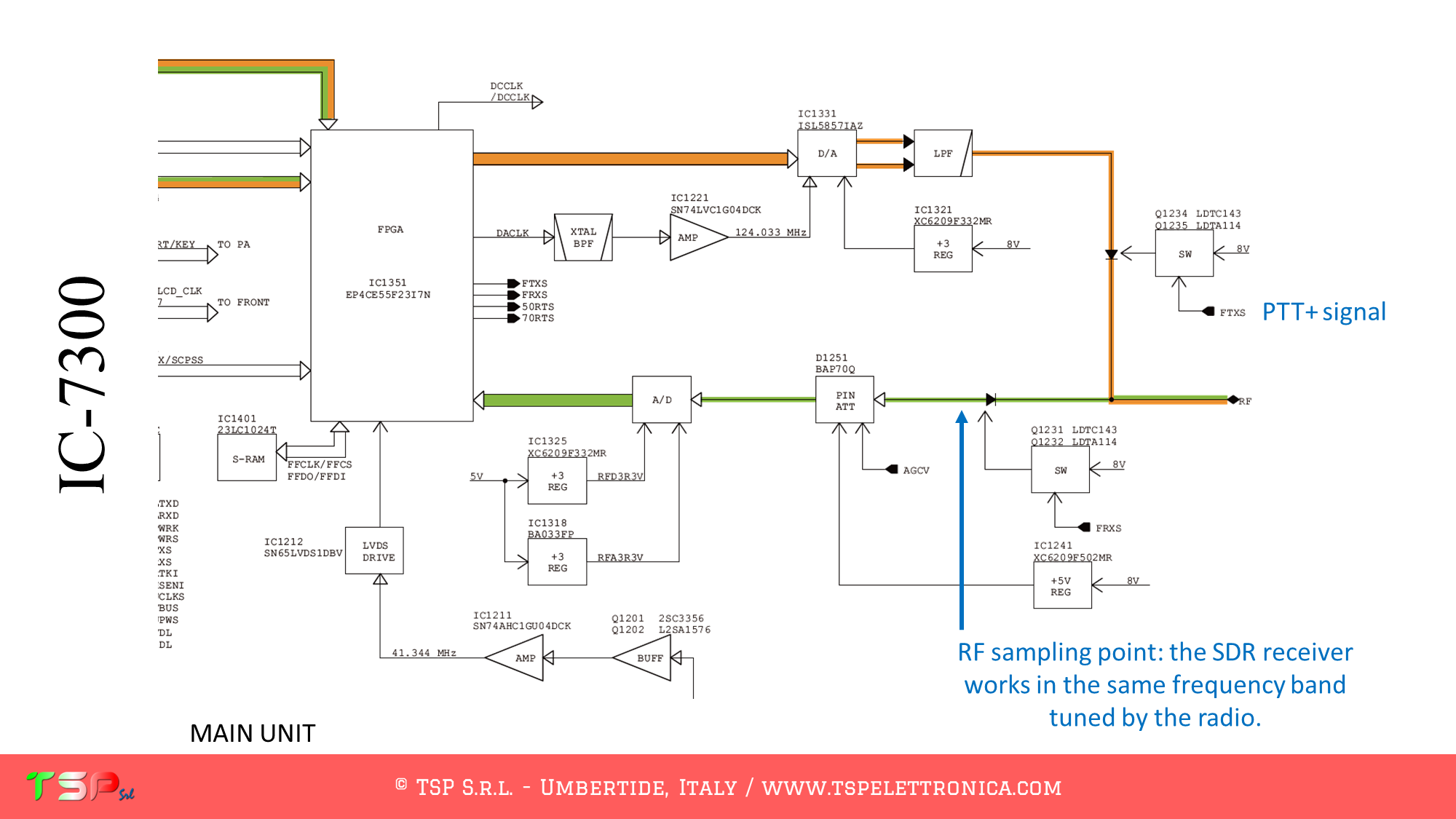
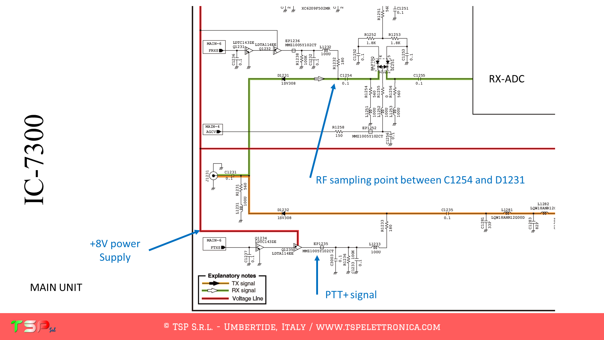
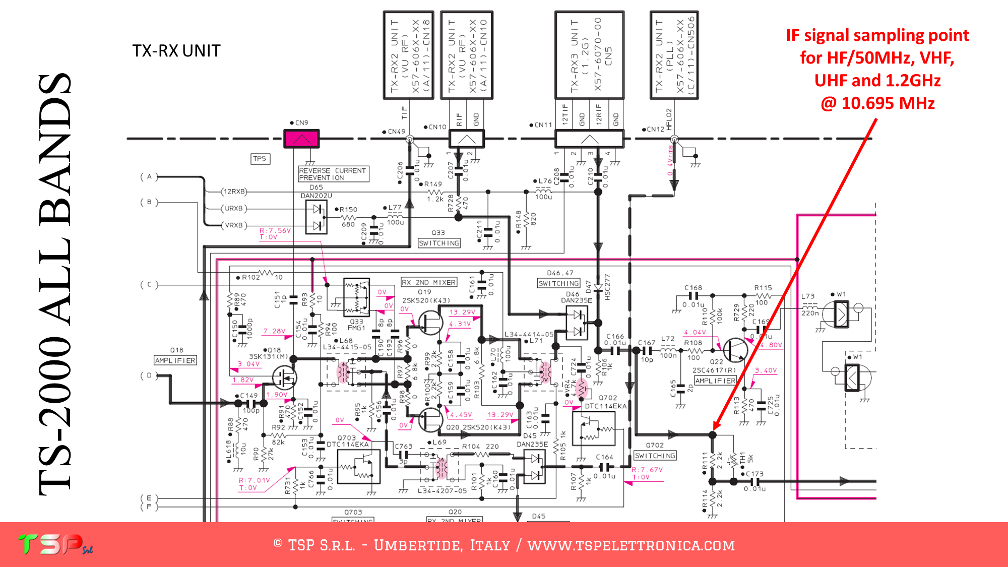
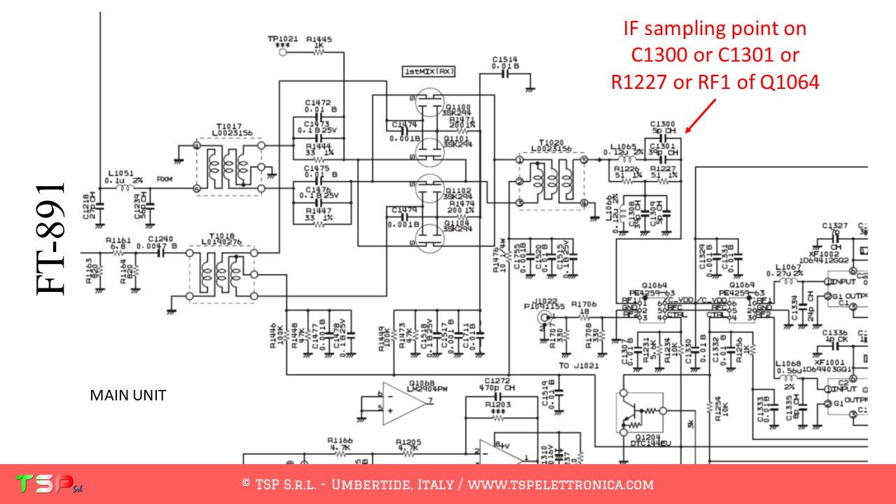
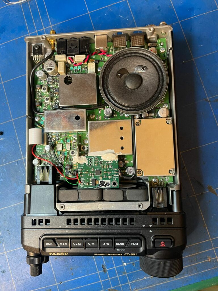
The RF signal at the mixer output is taken at the point shown in the following image.
The task of the IFace buffer card is to provide the power needed to correctly drive the external SDR receiver circuits: in practice, an impedance adaptation occurs between the mixer circuitry and that of the receiver. In general, the intensities of the signals of interest are small fractions of mW. During transmission, however, the powers are in the order of tens of W or even more, and this can be a problem for the external receiver, especially if it is working in isofrequency with the radio. Therefore, it is generally good to use the PTT signal to disable the buffer, a unique feature of the IFace, but this is not the case as the reception and transmission signals have different paths.
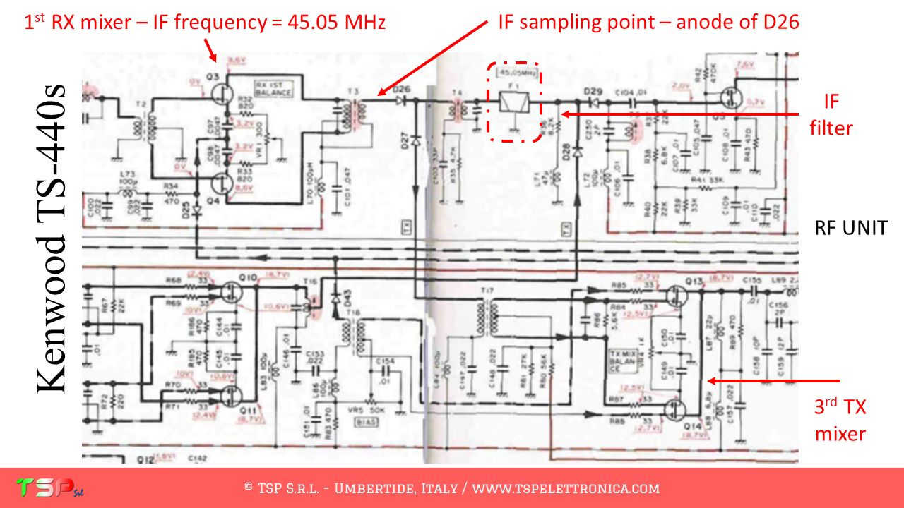
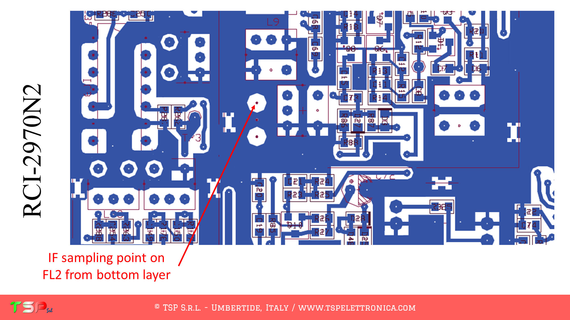
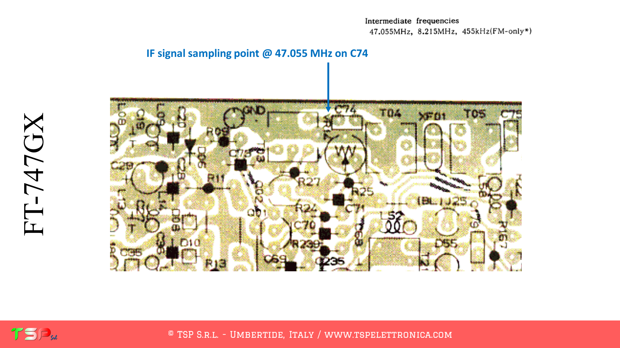
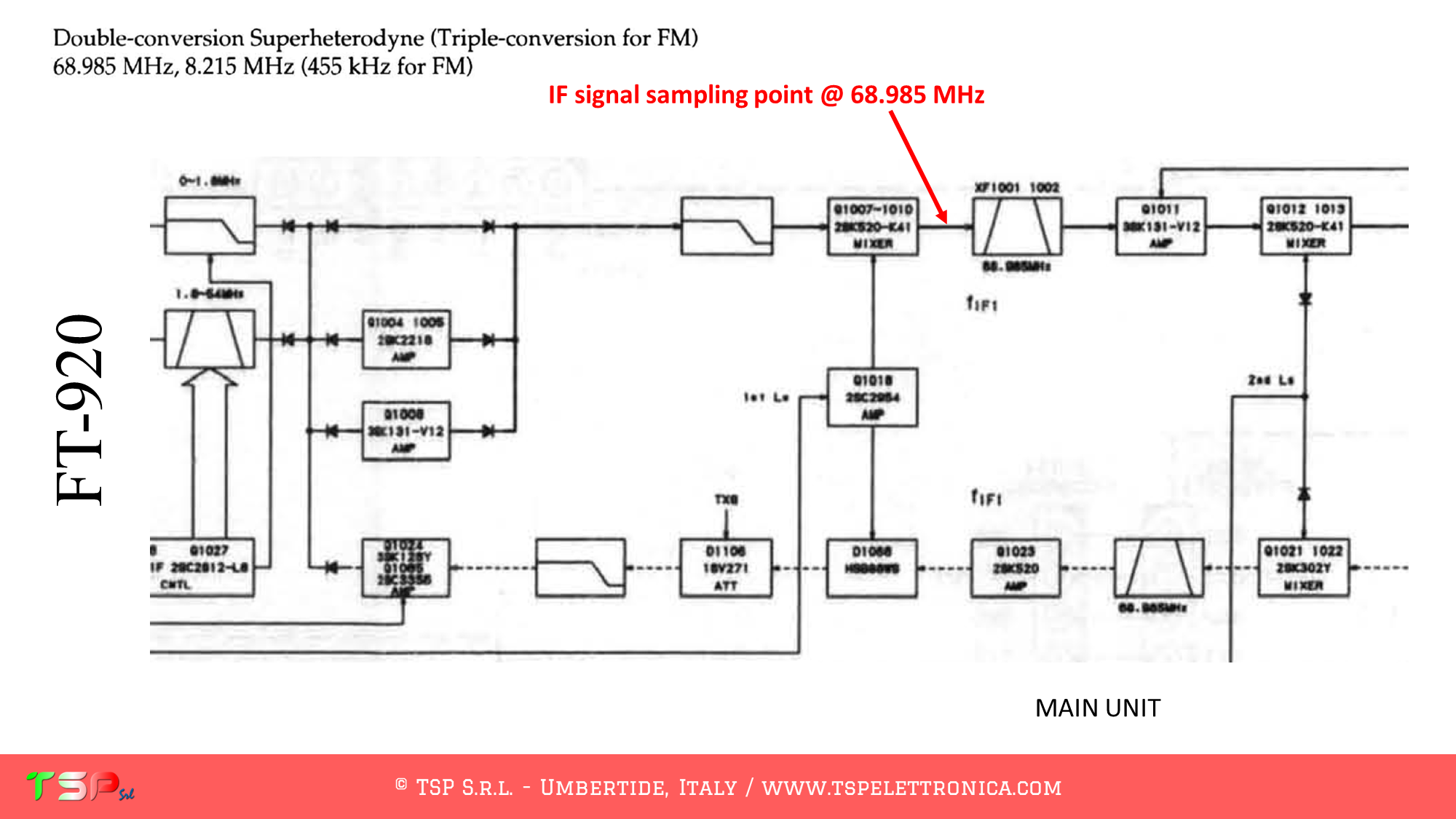
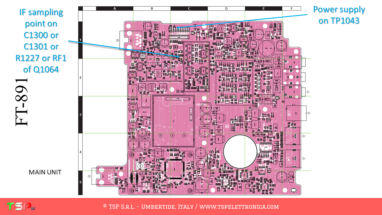
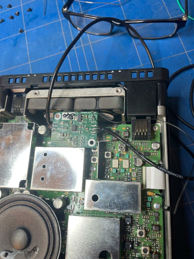
The following image shows where to take the IF signal.
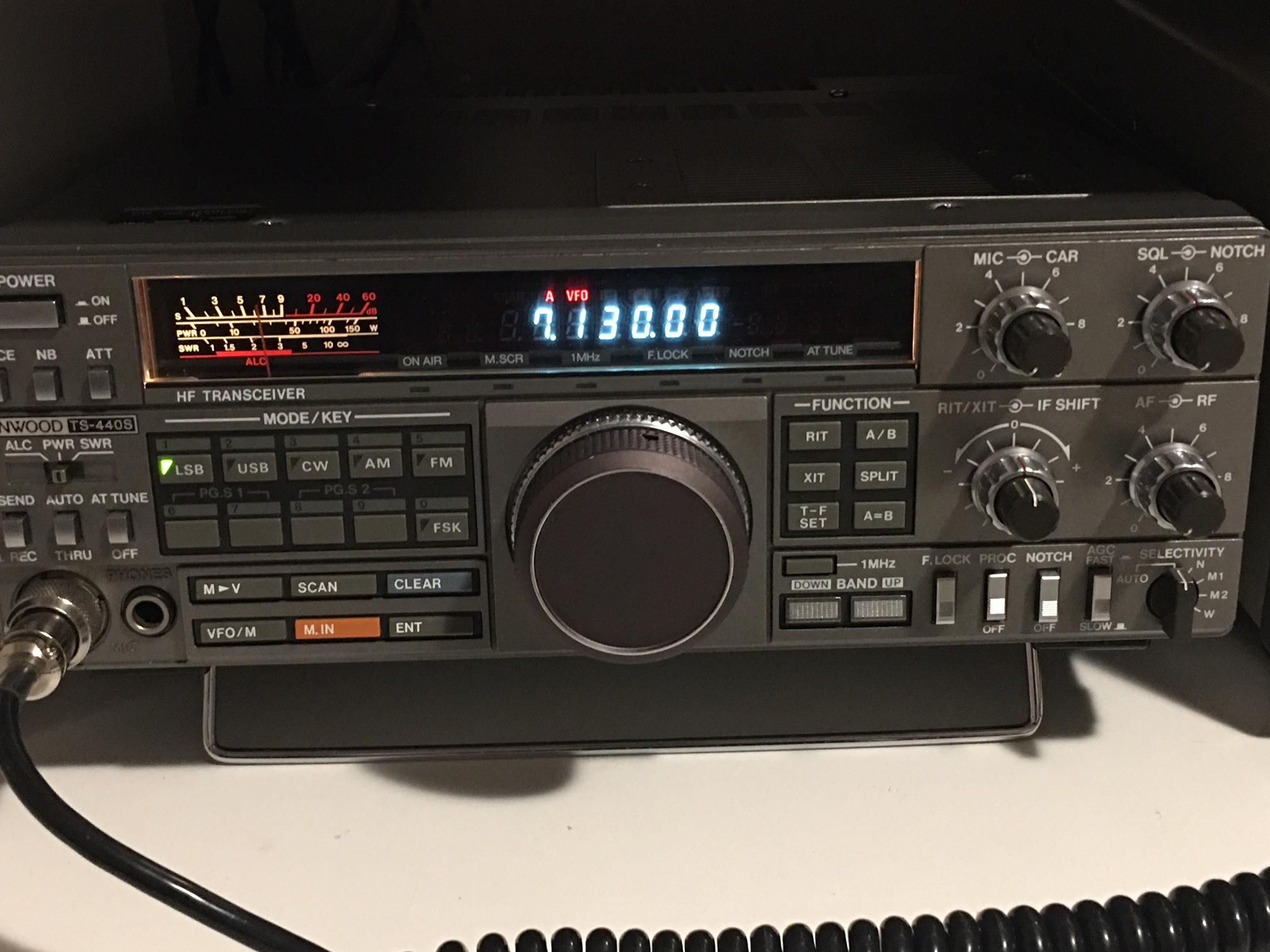
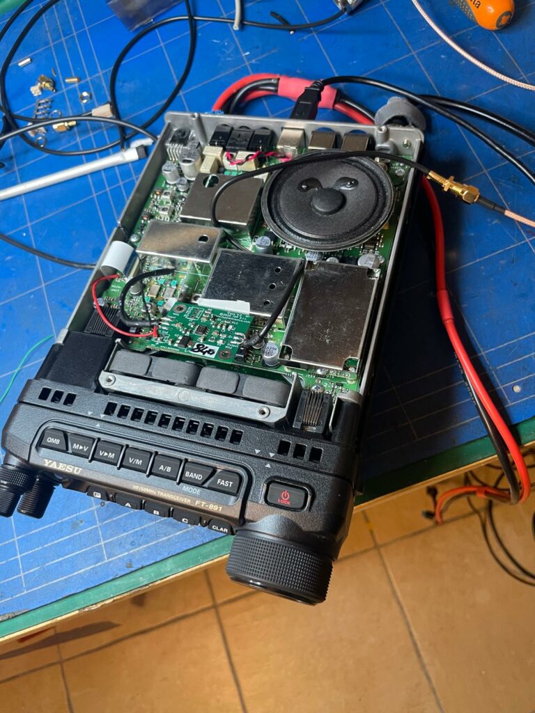
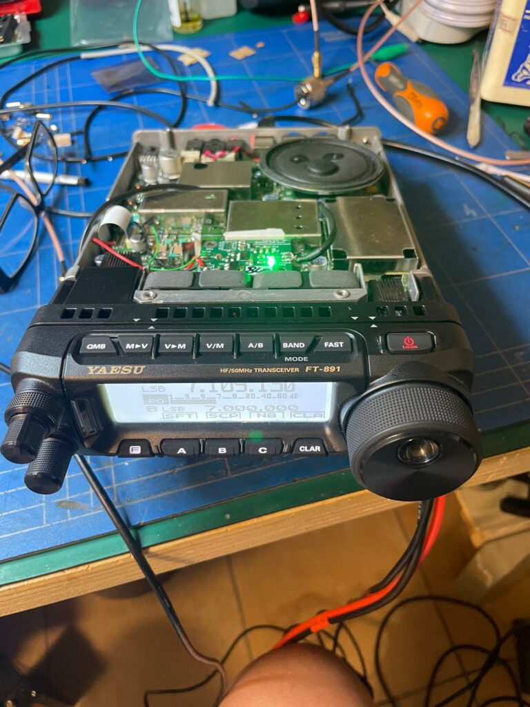
Below are some pictures of the installation done by IU7RAM.
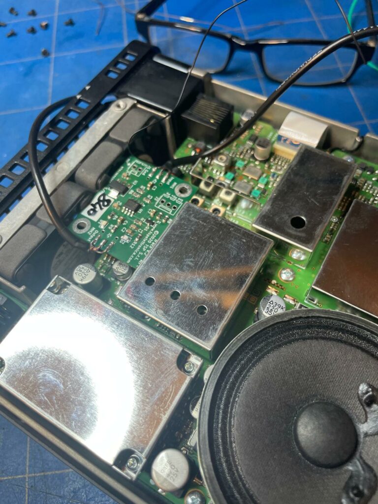
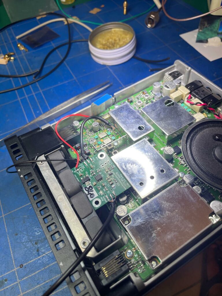
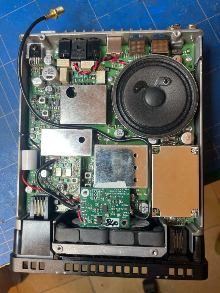
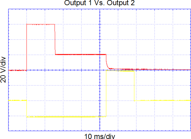
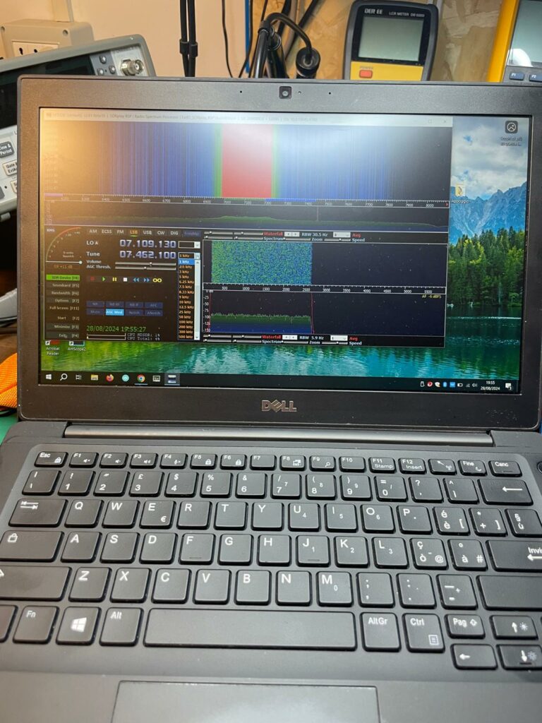
The following three images are from a first quick test during which it was verified that both the radio and the interface were working correctly.
As for the IF signal, it is worth noting that the use of a coaxial cable to connect the IFace input to the mixer output is not recommended. Its use involves the addition of a parasitic capacitance in parallel to the circuits downstream of the mixer with consequent degradation of the signal. Instead, it is good practice to use a small conductor, possibly very short, to reduce the aforementioned parasitic capacitance to a minimum.
This image shows how to connect the IF signal to the IFace. A thin conductor (0.14 mm) coated in green plastic material is used. As already highlighted (repetita iuvant), it is not recommended to use a coaxial cable because it introduces a non-negligible capacity in parallel to the components of the mixer circuit and would modify its performance. The coaxial cable can instead be safely used as an output from the IFace.
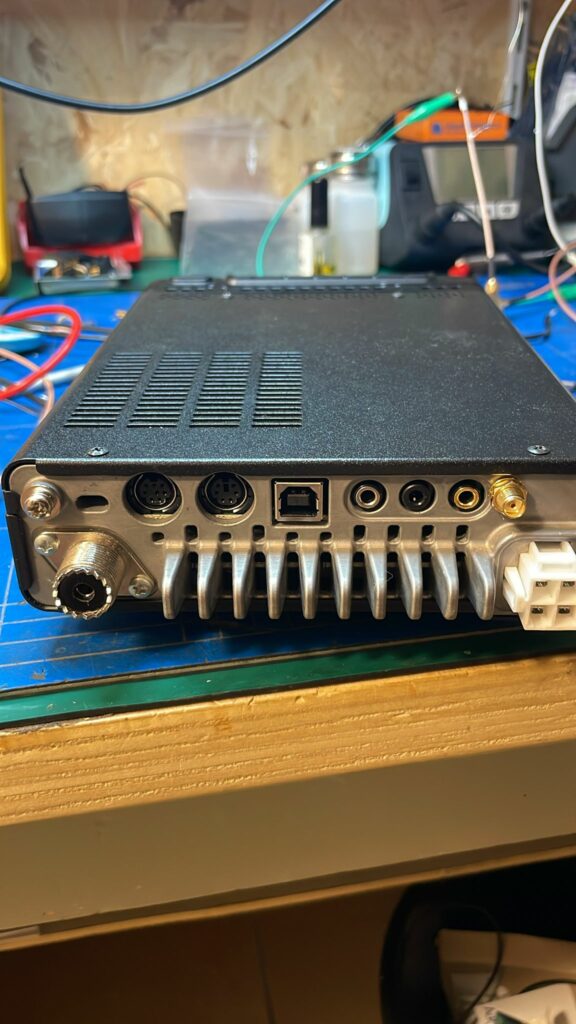
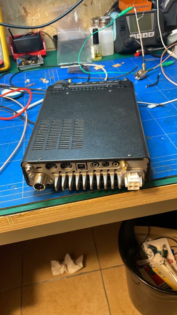
A small hole was drilled in the back of the radio to attach the SMA-f connector.
Once the work is completed, the result is shown in this short video.
Thank you very much IU7RAM Piero!
To purchase an IFace you can use the following buttons.

ATTENTION: Although the installation of IFace 2 is not difficult, it is done at your own risk. TSP S.r.l. is not responsible for any damage, unwanted side effects, or anything else.