This video course is only available in Italian language. Thank you.

This video course is only available in Italian language. Thank you.
Would you like to have a radio with a nice 40 “LCD display where you can view spectrograms, waterfalls and much more information? And what would you say to have a modern SDR radio so that you can listen to more signals at the same time? Wouldn’t it be nice to have many digital filters to improve reception during contest or DX activity?
If you answered yes then IFace 2 is the electronic card that allows you to have all of this without having to buy a new radio. How? By inserting it inside your “old” beloved RTX and using a cheap SDR receiver (for example those with a USB port you can connect to your computer).
IFace works with all the radios: click here!
Don’t you think so? Please watch this video and then keep reading.
The idea behind this product is to continue to use the radio that we have purchased and which has already given us so much satisfaction. Surely we already have the CAT interface with which we control it from the LOG or from other programs and we also have the audio interface for the digital modes. But sometimes we realize that we would need a second receiver (for example to follow the +5 kHz or + 10 kHz of a DX station), band filters with steeper sides to eliminate a disturbance on an adjacent frequency or a notch because our radio does not have it or it is not automatic. All this can be a memory!
So suppose to send the intermediate frequency signal (IF) of our radio to a dedicated SDR receiver and to start a program such as HDSDR (or SDR #, SDR Console …). On the screen of our computer we would have the spectrum display around the IF of our radio and, not to be neglected, we could also demodulate what it is receiving. But we could do even more, we could also demoulate other signals that are above or below the frequency tuned by our RTX.
Not bad, right?
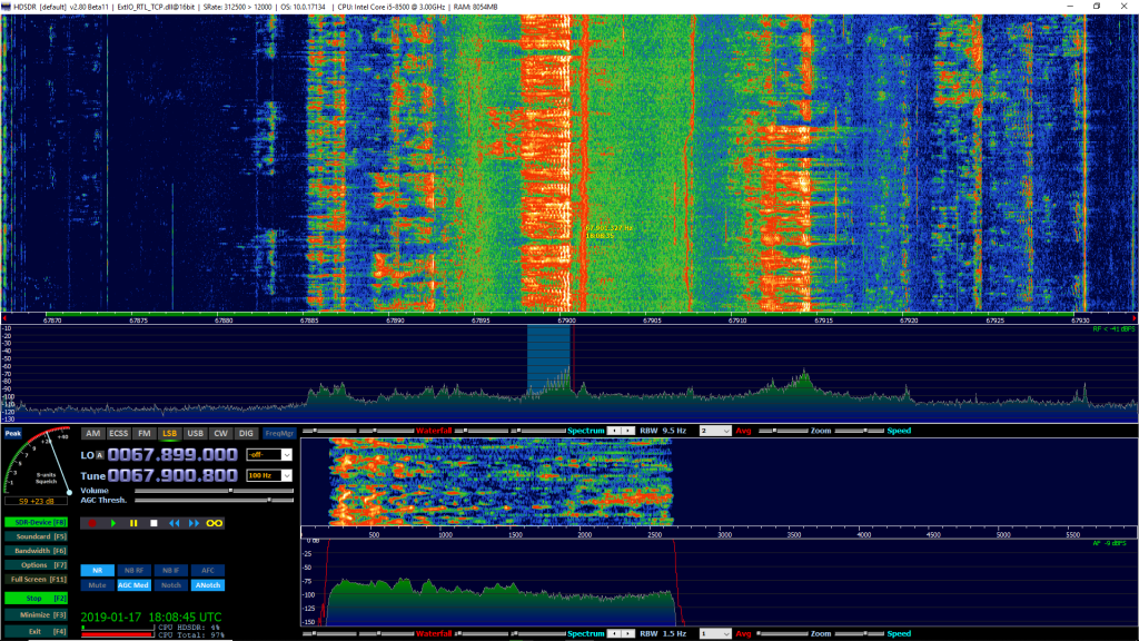
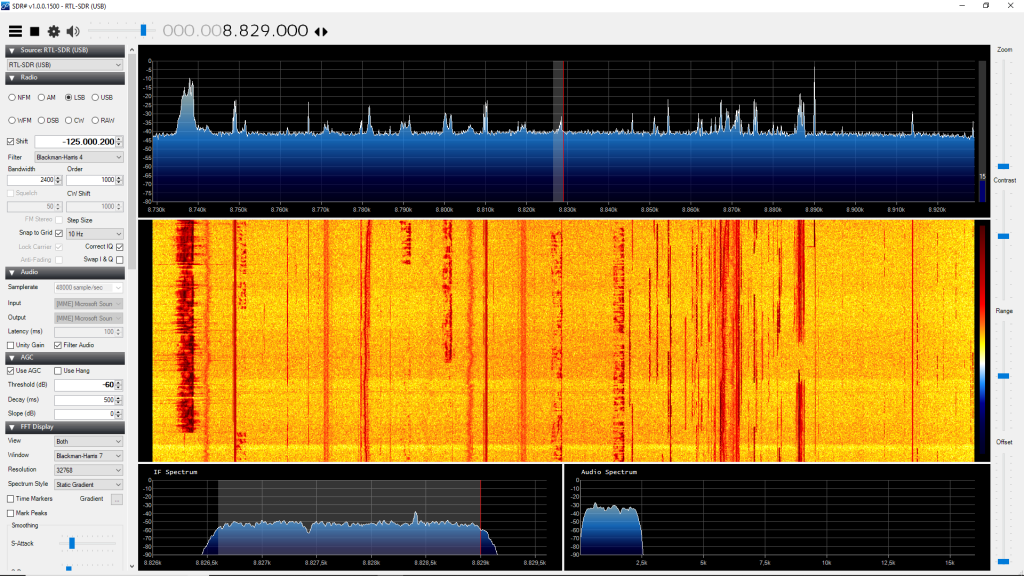
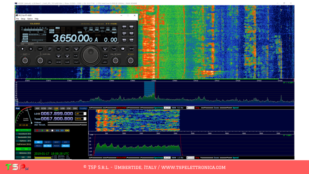
The image below shows a screenshot of HDSDR connected to an FT-450D via an RTL-SDR and the IFace.
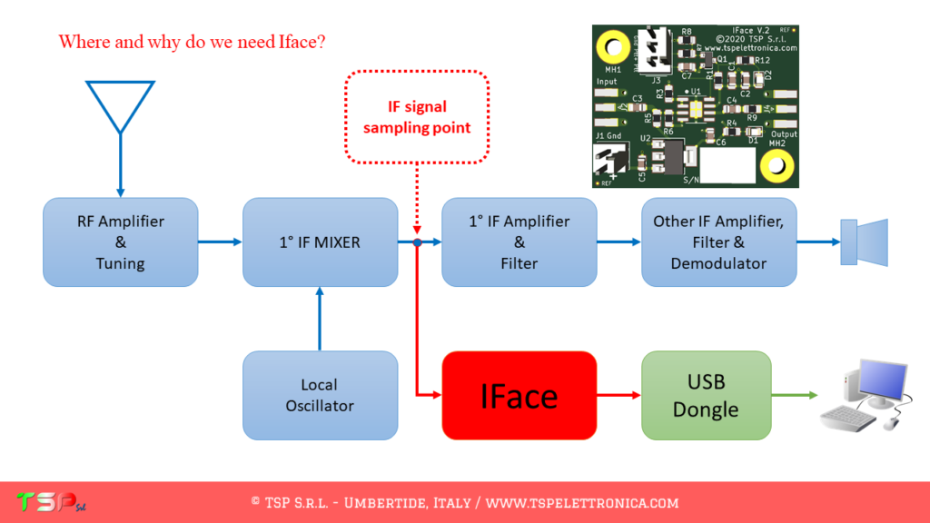
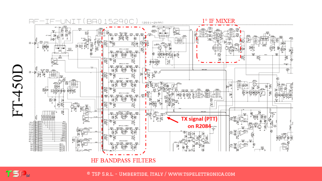
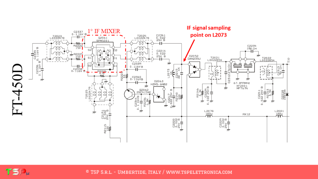
What needs to be done is very simple. Let’s start by identifying within our radio the point where to take the medium frequency signal. This is between the output of the first mixer and the subsequent bandpass filters as shown in the following image.
After connecting the IFace to the mixer output, we supply it with a voltage between 8 V and 15 V (from inside the radio) and connect it to an external SDR receiver. During the reception the difference is strong, listen here.
In order to not alter the operation of our receiver, we must pick up the signal without charging the mixer, i.e. without taking power. For this reason we have to insert a special card between this and the external receiver: we can not connect it directly. The IF signal pick up card, the IFace, creates a copy of the signal to be sent to the external SDR receiver. This is a wideband and no-tune buffer, i.e. no calibration is needed, it is installed and it is ready to work. The usefulness of this circuit is to allow the medium frequency signal to be replicated without increasing the load seen by the source (the mixer) and therefore without changing its performance.
Once the IF signal has been obtained, it is sufficient to connect the A / D converter (an RTL-SDR is already more than enough) to the USB port and start the software for the reception (ex HDSDR, SDR #, SDR Console etc) and our RTX will now be equipped with a nice panoramic receiver.
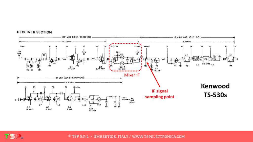
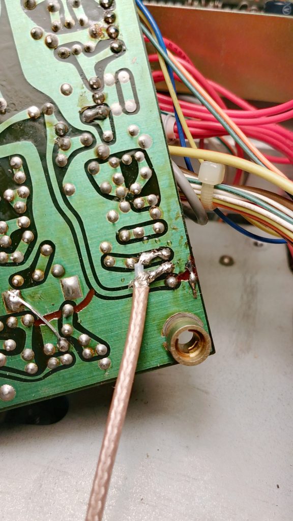
There are numerous advantages in picking up the IF signal and not the one coming directly from the antenna: one of these is surely the fact that the amplitude of the signal is controlled through the AGC circuitry of the reception stages. This helps to prevent saturation of the dynamics of RTL-SDR (which is not known to be the most extensive). The point where you take the IF signal is easy to find, just take the schematic diagram of your radio and look for the first mixer: at its output you will find the signal of interest. The image below shows the point where you have to connect the IFace interface in the case of a Kenwood TS-530s, a radio of a few decades ago, which can be easily updated with this interface.
The connection to the chosen point can be made with a thin coaxial cable (type RG178 or RG316) and will terminate at the “Input” pad of the IFace. If the connection is very short, a coaxial cable may not be necessary. The “Output” instead will be connected with another small coaxial cable to the input of the chosen SDR receiver. Obviously the buffer must be powered: it will not be difficult to find inside the radio a point where to draw a voltage of 9 Vdc or 12 Vdc. The following images show how easy it is to install the IFace into the TS-530s.
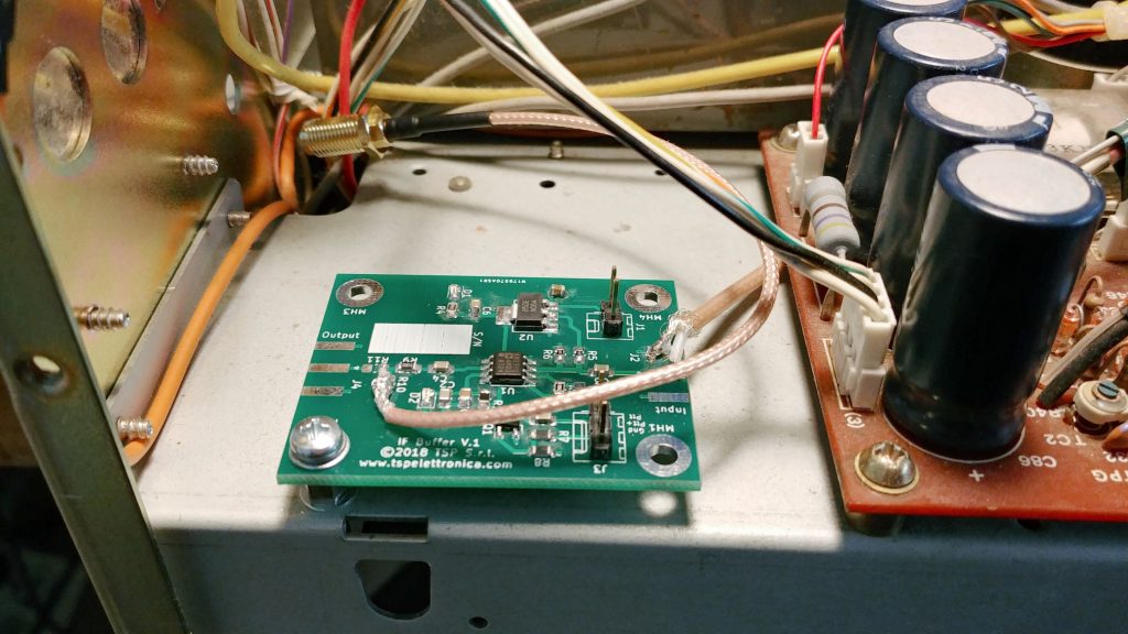
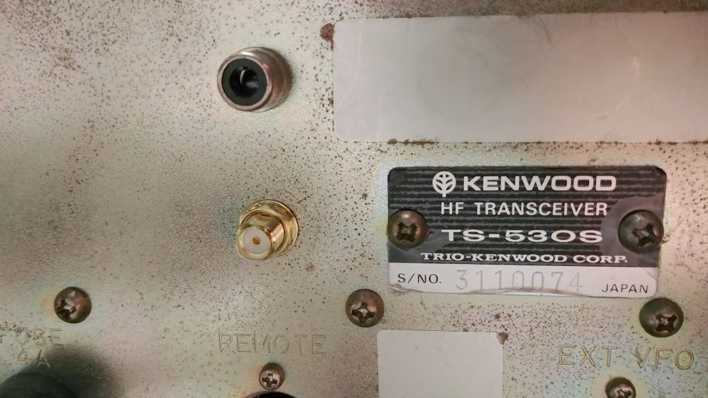
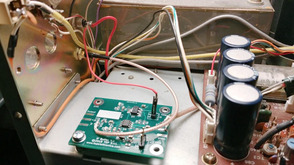
After making these simple wiring, you can connect your SDR receiver and start the reception software. The following image shows the SDR# screen during the reception with a Kenwood TS-530s (its intermediate frequency is 8.83 MHz) and an economical RTL-SDR.
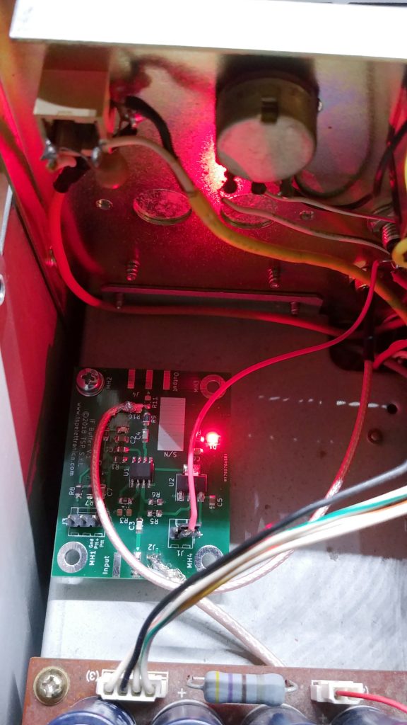
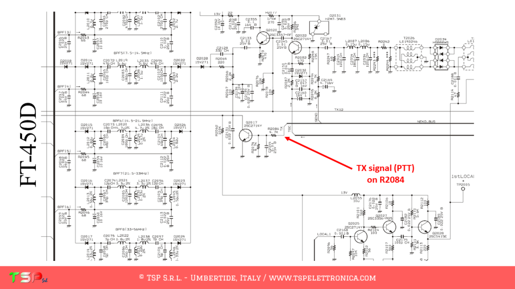
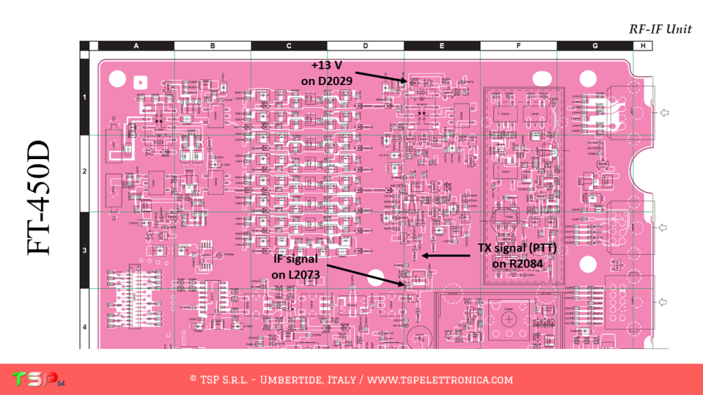
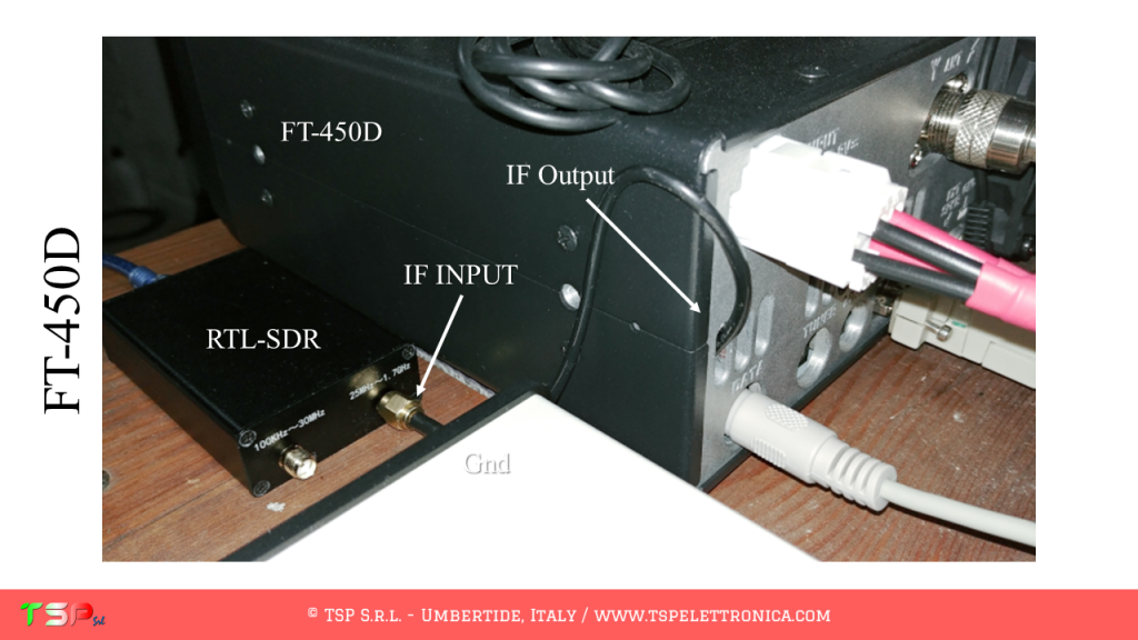
Another IFace has been installed in a YAESU FT-450D. As you will see from the photos, the space occupied is very little and the time required to connect the 4 conductors (+13 V, Gnd, Ptt +, IF) is a few minutes. In this case the Ptt signal was used, that is the “TX” signal present in the IF-UNIT of the radio. All this clearly appears in the following images.
IFace Vs IFace 2: because the differences are important!
IFace
IFace 2
In case you do not want to display any signal during transmission it is possible to turn off, by sending it into power down, the buffer of the IFace through a special input pin (PTT) as shown in the following picture. To be more accurate, an active high PTT, i.e. the signal is at a voltage greater than 5 V when transmitting, otherwise 0 V, or an active low PTT, i.e. the signal is at 0 V when the radio is transmitting, otherwise it must be floating, can be used.
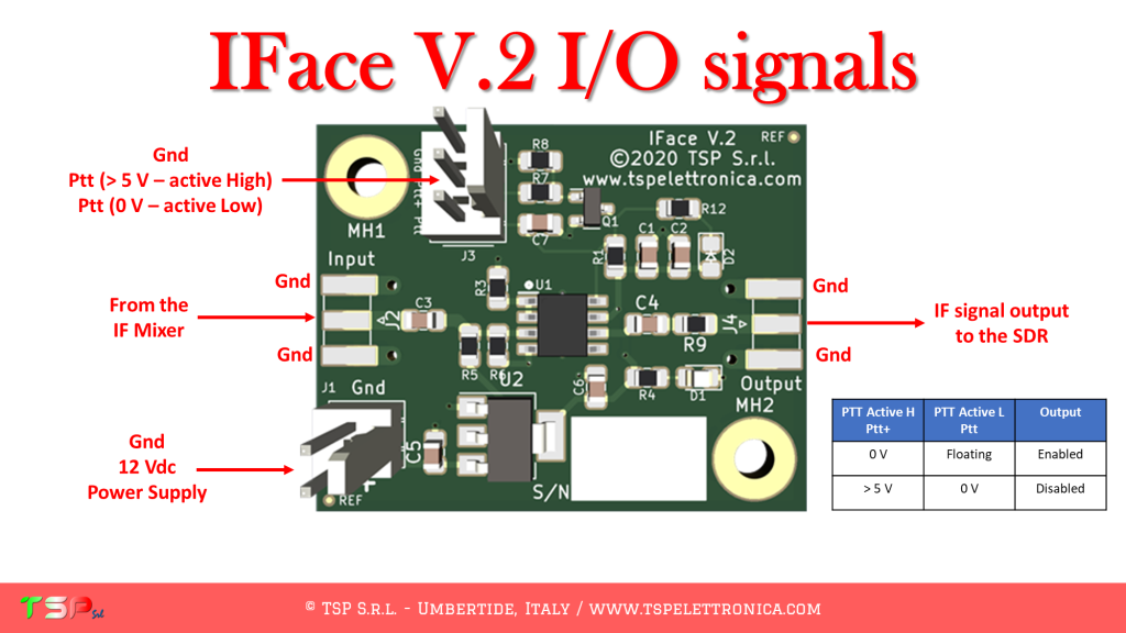
The following video shows how the card reacts to the pressure of the PTT, that is when the radio changes from reception to transmission: the red LED indicates that the card is in power-down because the radio is transmitting.
If you were still not convinced of the goodness of this interface look at this other video where you can see how the IFace works when added to an old Kenwood TS-530s.
Do you have any questions? Maybe we already have the answer you’re looking for.
Please read our Frequently Asked Questions – FAQ.
Isn’t it enough? We have some great testimonials!
TS-2000 SDR + RTL-SDR by IK0ZTL Alberto
IC-7600 SDR + RSP1A by EA5YJ Alfredo
IC-7100 SDR + RSPduo by IU8JAD Pellegrino
TS-870S SDR by IZ0ABD Francesco
HOW TO BUY IFACE 2
The price of IFace 2 is only € 37.62 excluding VAT (€45,90 for EU customers) + shipments costs for the “IFace + Cables” kit.
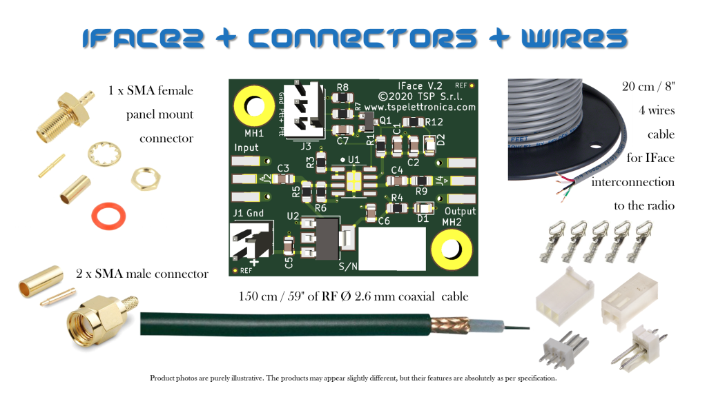
If you also want the coaxial connectors, those for the power supply and those for the PTT buy the “IFace 2 + Connectors + Cables” kit.
In this page you can find the list of the instructions to install the IFace into your radio: it is continuoursly growing. For those radios that are not included yet, send a request so that it can be entered as soon as possible.
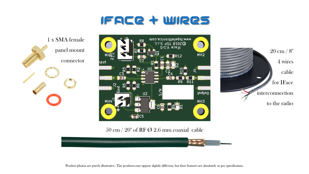
Content of the delivery “IFace + Cables”:
Content of the delivery “IFace 2 + Connectors + Cables”:
Order now by clicking on the following buttons and have fun.

ATTENTION: Though installing the IFace 2 is not difficult, you do this at your own risk. TSP S.r.l. is not responsible for any damage, unwanted side effects, or whatever.
If you have any questions, join the Telegram group dedicated to Amateur Radio by clicking here: Telegram Amateur Radio – English.
If you still have questions, use the following form, but don’t expect an immediate response, every day we receive many emails, including spam, so reading them is not a priority.
Thank you.
If you still have doubts about the validity of our CW Stick Paddle, read below the answers to the most frequent questions we have received so far.
Q. What is the difference between the “standard” version and the “Black & Gold Limited Edition” version?
A. The two keys are identical in terms of circuitry, that is, the difference is the finish, the first green, the second black, and the “touch” metallization, the first tin-plated, the second real gold-plated.
Q. Is it a resistive or capacitive key?
A. It is a resistive key, it works by exploiting the surface resistance of the skin. Extremely dry or hardened skins have a very high surface resistance and may not work well: in this case, moisturize it.
Q. How fast can you use it?
A. It depends on your skills, but in general, in the configuration sold, it works well at least up to 30 WPM or more. If you want to go much faster, above 40 WPM, you need to replace two resistors (currently 10 MOhm) with lower values.
D. Does it need for power?
R. No! The power supply is obtained directly from the “dash” and “dot” signals, there are no batteries that discharge.
Q. Does it work with all radios?
A. Yes, but it depends on the voltages on the “dot” and “dash” lines. In general, 5 V or voltages close to this value must be found on the wires and transmission must take place by grounding (GND) one of these lines.
For any other questions, use the form below. Thanks.
If you still have doubts about the validity of our IFace (click here), read below the answers to the most frequent questions we have received so far.

Q. What are the differences between IFace and IFace 2?
A. IFace and IFace 2 are 100% compatible. IFace 2 is an optimized version of IFace and is smaller. IFace 2 replaces the first version (which will no longer be sold).
Q. Can I continue to use the RTX without an SDR receiver connected to the IFace?
A. Obviously yes, the IFace does not influence the functioning of the radio in the least, it only serves to take a copy of the IF signal so that it can be sent to the external SDR receiver.
Q. What bandwidth can I see with the panadapter?
R. It depends, but above all, it does not depend on the IFace. It depends on the external SDR receiver you are going to use. For example, a classic RTL-SDR without decimation can typically reach 1 MHz bandwidth. An RSP1 can reach 10 MHz. If decimation is used, as we recommend, the band typically displayed is around 200 kHz (however more than enough for most applications).
Q. Is PTT necessary?
R. It depends, not always. It depends on the type of radio, in particular how the reception circuit is made. For example, if it uses part of the transmitter circuits then the answer is yes, otherwise if they are clearly separated the answer is no.
Q. What do “PTT Active High” and “PTT Active Low” mean?
A. Digital signals, such as the PTT signal, can be active high or active low. In the case of “active high” the PTT signal goes from 0 V to a higher value, typically 5 V or more. In the case of “active low,” the PTT signal goes from 5 or more volts to 0 V. Generally inside the radios the signal is “active high”. The “active low” signal is typical of an open-collector or open-drain transistor configuration.
Q. My radio does not have the CAT interface: at what frequency should the external SDR receiver be tuned?
A. In this case, if you do not use synchronization between computer and radio via CAT interface, the frequency to be used to receive correctly through the SDR panadapter is that of the IF to which the IFace is connected. Refer to the specific documentation for the installation of our interface.
Q. Can I use the CAT cable to change the frequency regardless of the VFO knob on the RTX or the software and have the same frequency value on both the SDR software and the radio?
A. Obviously yes, that’s what we recommend doing. If you use CAT to synchronize the radio and the SDR software, you will have full control of it directly from the computer screen.
Q. Where do I connect the coaxial cable braid to the IFace?
A. It can be connected to one of the holes on the PCB or, if coaxial connectors are not used, to one of the pads where the external part of the connector should be welded.
Q. I have an RTX that already has an IF output. If I connect my SDR there, would I get the same performance as if I used the IFace?
A. No. Generally, with IFace, the performances are better because we can connect it directly after the first IF mixer and before the roofing filter. This results in a band displayed on the screen that is much wider than that displayed on the radio’s IF output.
Q. What do you need besides your IFace card to have a complete panadapter?
A. In general, you need an A / D converter for RF signals, also called an SDR receiver (ex. RTL-SDR or SDRplay) and a special program for the computer (HDSDR, SDR Console, SDR #, SDRuno etc.). That’s it.
More questions? Please use the following form.

This video course is only available in Italian language. Thank you.
La crescente domanda di sistemi elettronici connessi alla rete Internet è oramai un dato di fatto. Progettare sistemi elettronici embedded in grado di inviare e ricevere informazioni dalla rete non è però la cosa più semplice da fare in quanto richiede conoscenze che spaziano dalla progettazione elettronica a quella sistemistica a quella di applicativi web.
Questo corso mostra come avviare e completare in modo professionale un progetto basato sul modulo ESP8266 e sull’IDE Arduino.
Che tu voglia realizzare un dispositivo per semplice diletto o per un’applicazione industriale, in questo corso troverai tutte le informazioni di cui avrai bisogno per procedere speditamente dall’idea al prodotto finale senza commettere errori.
Non ci credi?
Hai mai provato a cercare una libreria per un sensore? L’hai trovata e provando ad utilizzarla ti sei accorto che non funziona? Bene, non sei l’unico a cui è capitato. Purtroppo forum e blog di hobbisti di tutto il mondo sono pieni di errori, materiale scadente e di dubbia provenienza, pochi, veramente pochi, contengono informazioni corrette e pronte da utilizzare. Questo accade perché nel mondo dei microcontrollori c’è una grande confusione in quanto la semplificazione dei tool di sviluppo ha abbassato notevolmente il livello delle conoscenze richieste per utilizzare un particolare dispositivo. Ma utilizzare e saper programmare sono due cose ben diverse.
Trovare informazioni affidabili è estremamente raro.
Per tua fortuna questo corso è la soluzione a tutti questi problemi perché è basato su ciò che è stato realmente fatto per sviluppare una nostra scheda elettronica per applicazioni industriali di IoT, la WiWiNo One.
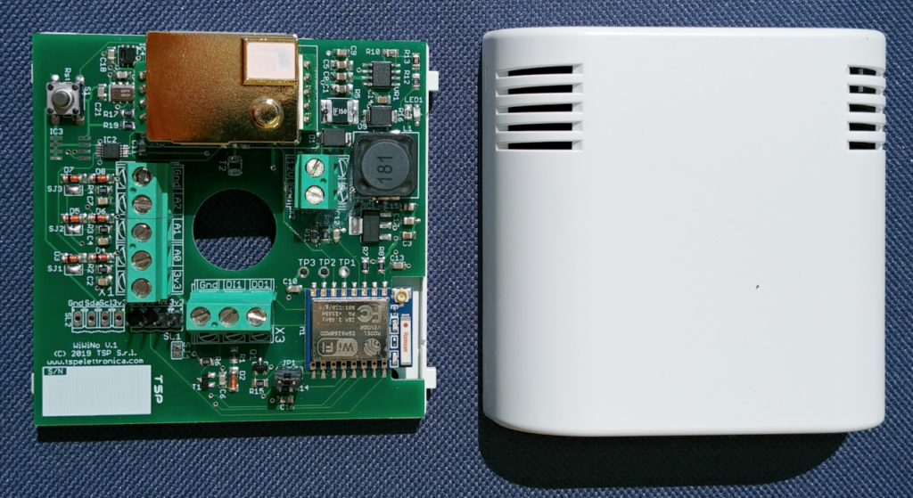
La scheda in questione, che vedi anche nell’immagine qui sotto, integra un modulo ESP8266-07, una serie di sensori di temperatura, umidità, pressione atmosferica, CO2. Sono inoltre disponibili 3 ingressi analogici 0-3,3 V, un’uscita digitale open-drain ed un ingresso digitale 0-24 Vdc. Per l’alimentazione è utilizzato un regolatore switching così che si può utilizzare con sorgente da 8 a 30 Vdc.
A chi si rivolge il corso
Per chi NON è adatto questo corso
Le lezioni contenute nel videocorso sono le seguenti:
Ecco qui l’offerta esclusiva a cui puoi accedere.
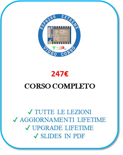
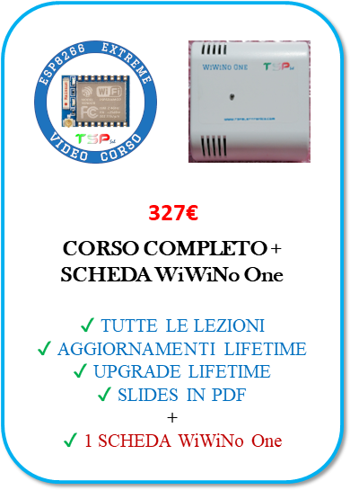
Il corso sarà acquistabile a questo prezzo per un periodo limitato e fruibile al termine di questo ( 15 Settembre 2019 ). Si può acquistarlo ad un prezzo ancora più vantaggioso insieme all’evento “TSP Training Days”, due giorni in aula il 30/11 e 1/12/2019 per imparare a saldare componenti SMD e programmare Arduino in modo professionale per applicazioni IoT. Dopo questa data il costo salirà.
Per “aggiornamento” di una lezione si intende un miglioramento del contenuto: ad esempio potrebbero essere aggiunte o modificate delle slide e con queste la loro descrizione.
Per “updates” del corso si intende l’inserimento di nuove lezioni.
N.B. Come stabilito dal Codice del Consumo, art. 59, lettera o, il diritto di recesso non si applica a “la fornitura di contenuto digitale mediante un supporto non materiale se l’esecuzione è iniziata con l’accordo espresso del consumatore e con la sua accettazione del fatto che in tal caso avrebbe perso il diritto di recesso”.
This short acticle refers to another article you can find at this address: https://iz0abd.wordpress.com/2019/05/28/beacon-ardf-a-433-92-mhz/
Those who wish to purchase the PIC12F509 microcontroller already programmed to periodically generate an “S” in Morse code can do so through the button shown below.
For any other detail please visit https://iz0abd.wordpress.com/2019/05/28/beacon-ardf-a-433-92-mhz/ or simply send us your request using the form in the contacts section.
Enjoy

Electronic Maker Hiker is only available in Italian language. Thank you.
IFace 2 has arrived: the same cost, better performance and smaller. Discover it now!
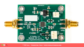
Would you like to have a radio with a nice 40 “LCD display where you can view spectrograms, waterfalls and much more information? And what would you say to have a modern SDR radio so that you can listen to more signals at the same time? Wouldn’t it be nice to have many digital filters to improve reception during contest or DX activity? If you answered yes then IFace is the electronic card that allows you to have all of this without having to buy a new radio. How? By inserting it inside your “old” beloved RTX and using a cheap SDR receiver for computers (some suggestions here) such as an USB RTL-SDR dongles.
IFace works with all the radios!
Don’t you think so? Please watch this video and then keep reading.
The idea behind this product is to continue to use the radio that we have purchased and which has already given us so much satisfaction. Surely we already have the CAT interface with which we control it from the LOG or from other programs and we also have the audio interface for the digital modes. But sometimes we realize that we would need a second receiver (for example to follow the +5 kHz or + 10 kHz of a DX station), band filters with steeper sides to eliminate a disturbance on an adjacent frequency or a notch because our radio does not have it or it is not automatic. All this can be a memory!
So suppose to send the intermediate frequency signal (IF) of our radio to a dedicated SDR receiver and to start a program such as HDSDR (or SDR #, SDR Console …). On the screen of our computer we would have the spectrum display around the IF of our radio and, not to be neglected, we could also demodulate what it is receiving. But we could do even more, we could also demoulate other signals that are above or below the frequency tuned by our RTX.
Not bad, right?
The image below shows a screenshot of HDSDR connected to an FT-450D via an RTL-SDR and the IFace.

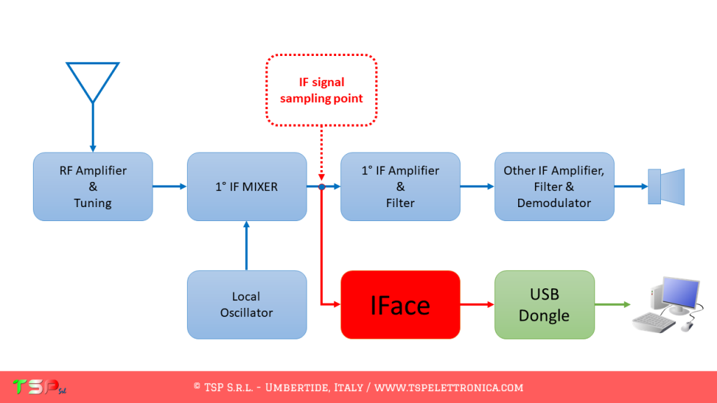
What needs to be done is very simple. Let’s start by identifying within our radio the point where to take the medium frequency signal. This is between the output of the first mixer and the subsequent bandpass filters as shown in the following image.
During the reception the difference is strong, listen here.
In order to not alter the operation of our receiver, we must pick up the signal without charging the mixer, i.e. without taking power. For this reason we have to insert a special card between this and the external receiver: we can not connect it directly. The IF signal pick up card, the IFace, creates a copy of the signal to be sent to the external SDR receiver. This is a wideband and no-tune buffer, i.e. no calibration is needed, it is installed and it is ready to work. The usefulness of this circuit is to allow the medium frequency signal to be replicated without increasing the load seen by the source (the mixer) and therefore without changing its performance.
Once the IF signal has been obtained, it is sufficient to connect the A / D converter (an RTL-SDR is already more than enough) to the USB port and start the software for the reception (ex HDSDR, SDR #, SDR Console etc) and our RTX will now be equipped with a nice panoramic receiver.
Are you already convinced? Very well, buy an IFace immediately by clicking on the buttons below!

There are numerous advantages in picking up the IF signal and not the one coming directly from the antenna: one of these is surely the fact that the amplitude of the signal is controlled through the AGC circuitry of the reception stages. This helps to prevent saturation of the dynamics of RTL-SDR (which is not known to be the most extensive). The point where you take the IF signal is easy to find, just take the schematic diagram of your radio and look for the first mixer: at its output you will find the signal of interest. The image below shows the point where you have to connect the IFace interface in the case of a Kenwood TS-530s, a radio of a few decades ago, which can be easily updated with this interface.

The connection to the chosen point can be made with a thin coaxial cable (type RG178 or RG316) and will terminate at the “Input” pad of the IFace. If the connection is very short, a coaxial cable may not be necessary. The “Output” instead will be connected with another small coaxial cable to the input of the chosen SDR receiver. Obviously the buffer must be powered: it will not be difficult to find inside the radio a point where to draw a voltage of 9 Vdc or 12 Vdc. The following images show how easy it is to install the IFace into the TS-530s.
After making these simple wiring, you can connect your SDR receiver and start the reception software. The following image shows the SDR# screen during the reception with a Kenwood TS-530s (its intermediate frequency is 8.83 MHz) and an economical RTL-SDR.

Another IFace has been installed in a YAESU FT-450D. As you will see from the photos, the space occupied is very little and the time required to connect the 4 conductors (+13 V, Gnd, Ptt +, IF) is a few minutes. In this case the Ptt signal was used, that is the “TX” signal present in the IF-UNIT of the radio. All this clearly appears in the following images.
The main characteristics of the IFace are:
In case you do not want to display any signal during transmission it is possible to turn off, by sending it into power down, the buffer of the IFace through a special input pin (PTT) as shown in the following picture. To be more accurate, an active high PTT, i.e. the signal is at a voltage > 5 V when transmitting, otherwise 0 V, or an active low PTT, i.e. the signal is at 0 V when the radio is transmitting, otherwise it must be floating, can be used.
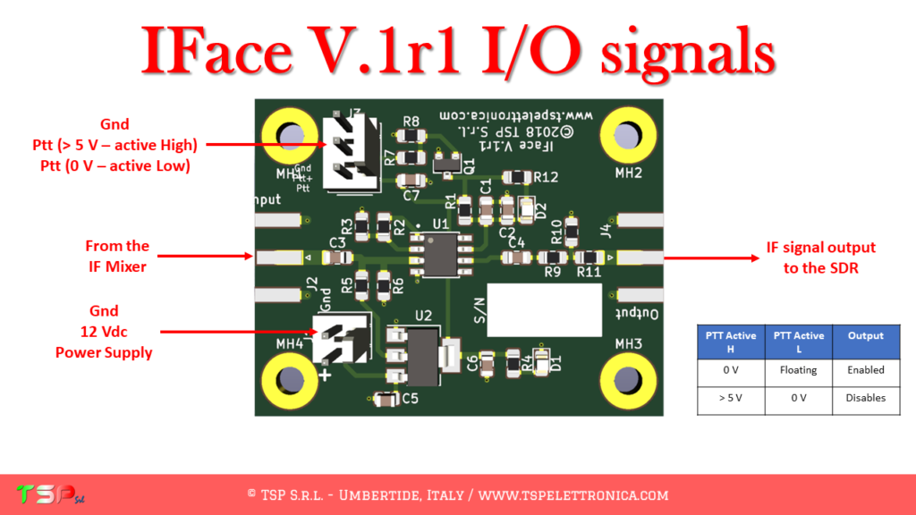
The following video shows how the card reacts to the pressure of the PTT, that is when the radio changes from reception to transmission: the red LED indicates that the card is in power-down because the radio is transmitting.
If you were still not convinced of the goodness of this interface look at this other video where you can see how the IFace works when added to an old Kenwood TS-530s.
Do you have any questions? Maybe we already have the answer you’re looking for.
Please read our Frequently Asked Questions – FAQ.
Isn’t it enough? We have some testimonials!
TS-2000 SDR + RTL-SDR by Alberto IK0ZTL
IC-7600 SDR + SDR1A by Alfredo EA5YJ
IC-7100 SDR + RSPduo by Pellegrino IU8JAD
HOW TO BUY IFACE
The price of IFace is only € 42.90 including VAT + shipments costs for the “IFace + Cables” kit. If you also want SMA coaxial connectors, those for power supply and those for the PTT buy the “IFace + Connectors + Cables” kit for only € 54.90 VAT + shipping costs.
There’s a third option, “IFace + Connectors + SDR Panadapter”. This comprises a powerful 12 bit/sa 10 MHz panadapter that will bring your receiving experience to another level. And it is compatible with the RSP1 from SDRplay: you can use the software SDRuno. This kit costs only €104.90 + shipment.
In this page you can find the list of the instructions to install the IFace into your radio: it is continuoursly growing. For those radios that are not included yet, send a request so that it can be entered as soon as possible.
Content of the delivery “IFace + Cables”:
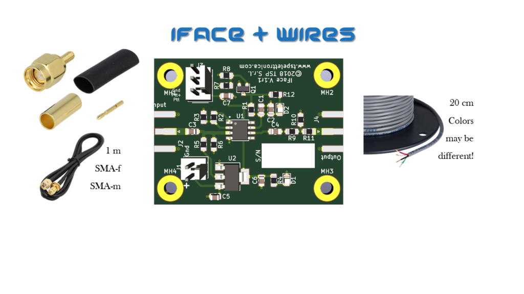
Content of the delivery “IFace + Cables”:

Order now by clicking on the following buttons and have fun.

ATTENTION: Though installing the IFace is not difficult, you do this at your own risk. TSP S.r.l. is not responsible for any damage, unwanted side-effects or whatever.
Any question? Please use the following form.
CW Stick Paddle 2 is a simple and easy to use Morse code keyer thought to be light, small and inexpensive. With respect the previous version, this adds the squeeze mode feature.
It is ideal for portable and QRP operations, in car installations, but also for travelling everywhere you want with your favourite radio.
It doesn’t have mechanical parts, it is totally electronic. And it doesn’t need any battery to work! Use simply your fingers to start operating Morse code with your favourite radio.
It works with all the modern transceivers replacing a normal mechanical 3 wires Morse keyer.
It is available in two versions, the “standard” and the “Black & Gold Limited Edition”, elegant and beautiful !!!

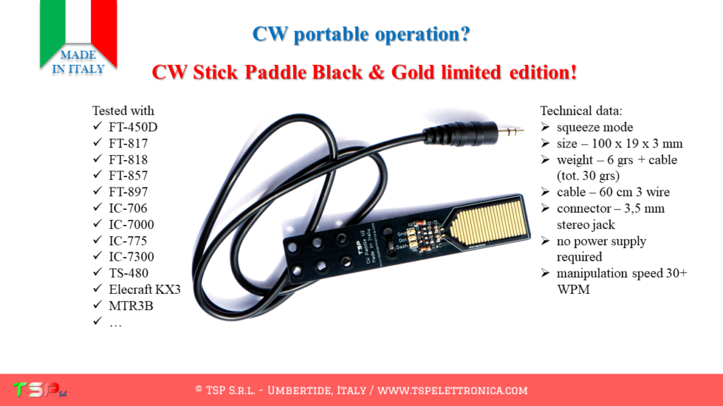
It can be used with FT-450D, FT-817, FT-857, FT-897, IC-706, IC-7000, IC-7300, TS-480, Elecraft KX3, Mountain Topper Radio MTR3B and similar (low voltage (3 – 5 V) on keyer connector).
Technical data:
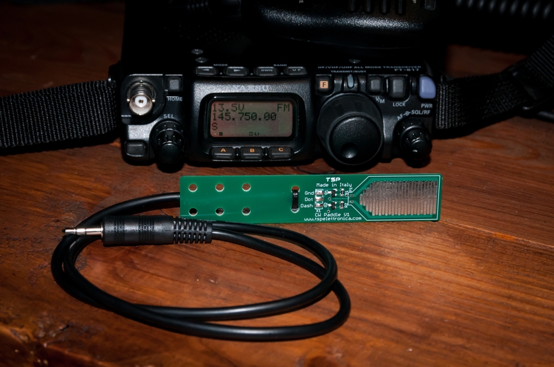
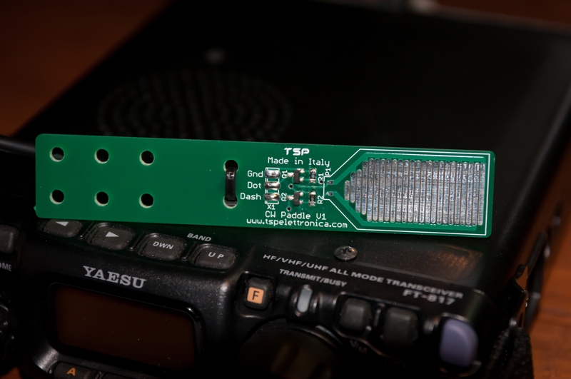
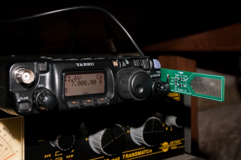
Do you like it? Buy one (or more) by pressing one of the following buttons.

Want more information? Please read the FAQ (click here) or please watch these demo videos.
If you have questions please use the following form.