February 23, 2021

Panadapter SDR for the IC-781 with IFace v.2

Another very important testimonial has been sent to us by IZ4AQT Nicola and we can never say “thank you very much” enough. Here below we propose his full report.

https://youtu.be/W_3kcYuYjO8

This description is intended to be complementary to the article already published for the same apparatus modified with IFace v.1. The solution described here advantageously takes advantage of the small size that the IFace v.2 interface “without connectors” has; in particular, the extremely limited thickness of the SMD construction made it possible to choose a location inside the “shielded box” of the RF Unit. Having used a rather rigid shielded cable (RG 316 / U), and the sampling point of the IF signal being particularly hidden, particular care had to be taken in the path and execution of the solderings. Primary objective: we must have curves of the coaxial cable sufficiently wide so as not to create excessive stress on the welding points. The photos below show the sequence of the implementation steps of the change.

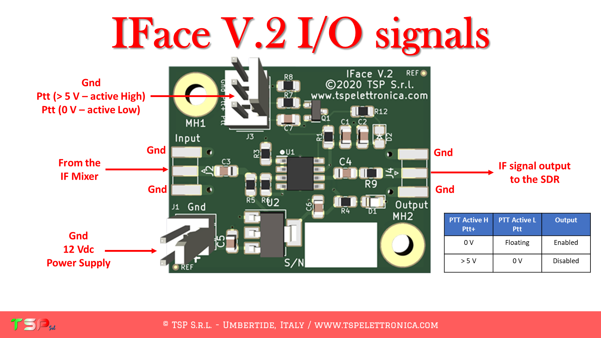
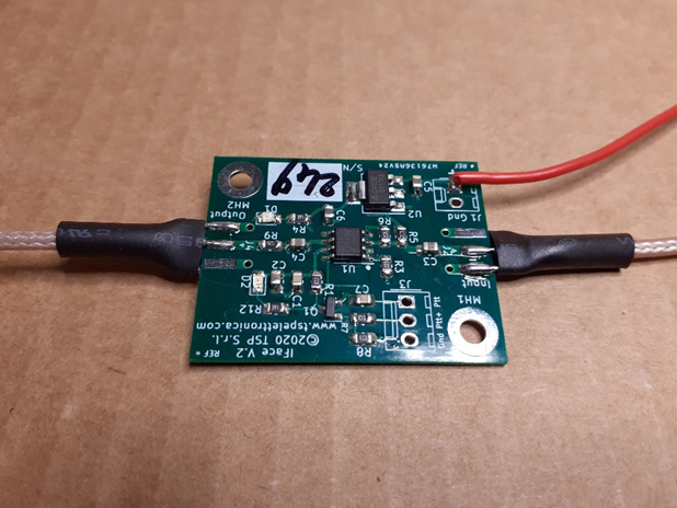
Preparing the IFace for installation

In this phase the coaxial input and output signal cables and the power supply cable (in red) have been soldered to the board.

Check the overall dimensions in the final position

In this phase it was checked that the IFace v.2, suitably sandwiched between two insulating layers of plasticized cardboard, could easily find its place inside the RF Unit compartment.

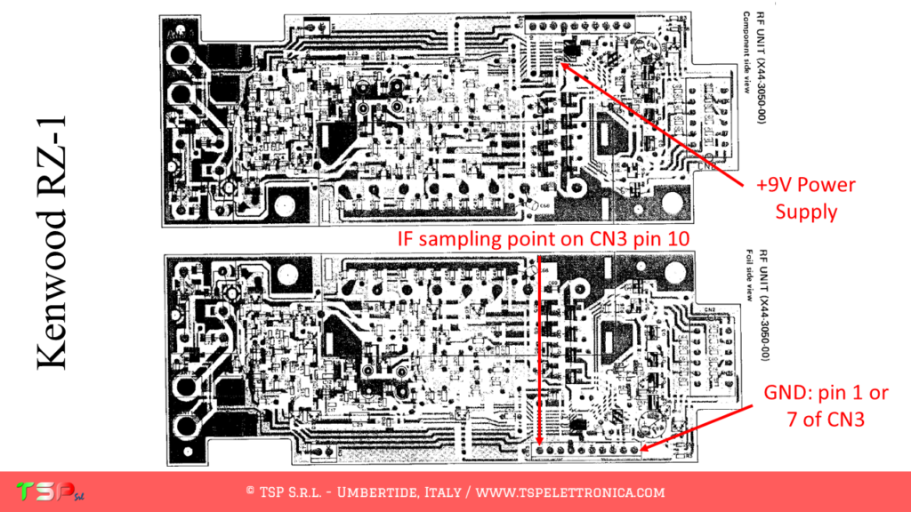
Welding of the IF pickup cable

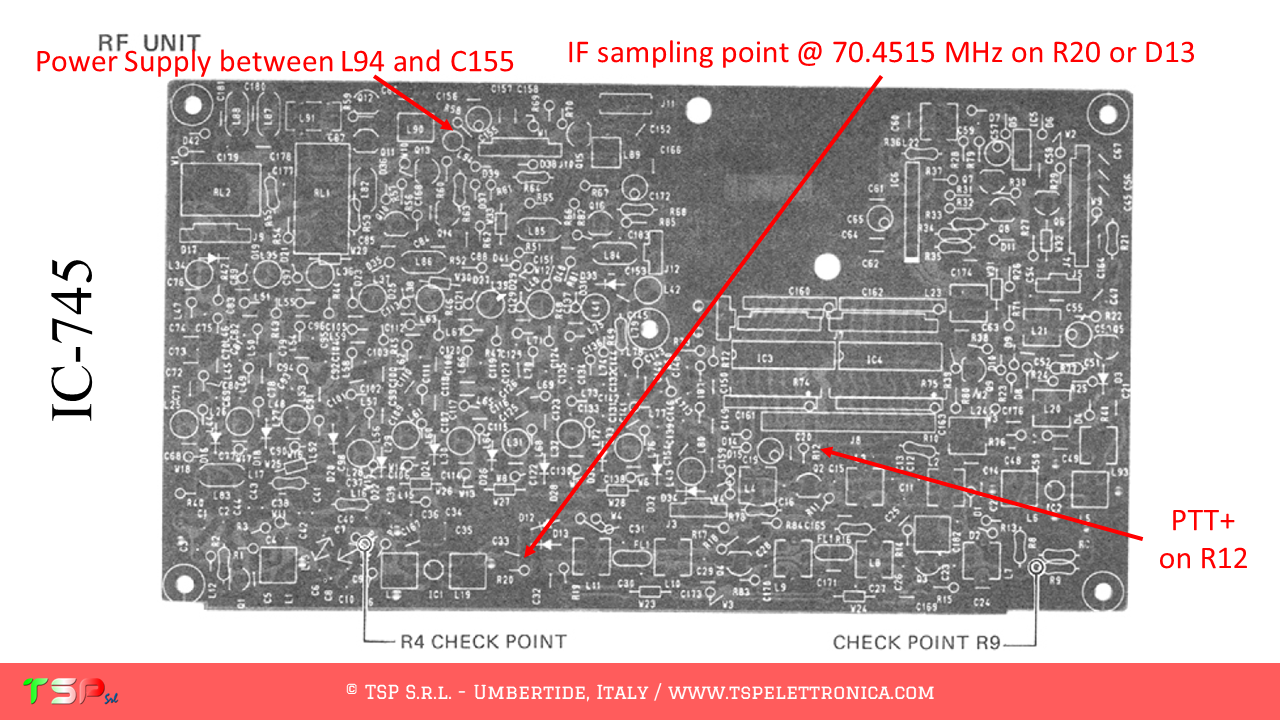
To facilitate soldering of the IF pickup cable, the RF Unit board has been removed from its housing so that the contacts on its underside can be easily accessed. The image below shows the solder side of this board.

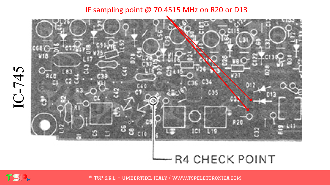
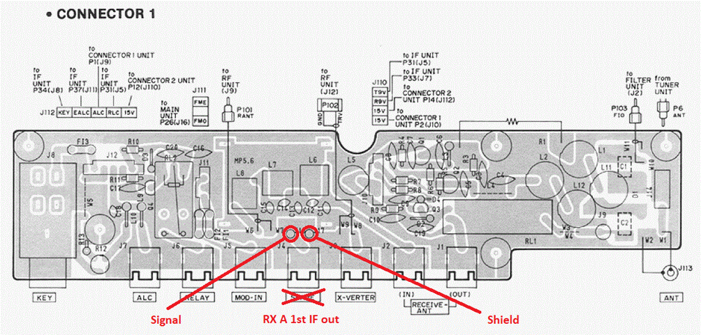
The points where to carry out the soldering to take the IF signal and the power supply are shown in the following image. It should be noted that the welding, for convenience, will then be carried out on the lower side.

Uscita del segnale IF

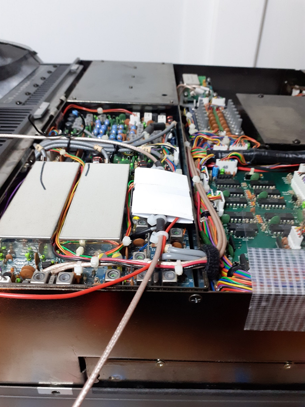
In this image you can see the Teflon coaxial cable (RG 316 / U) for the output of the IF signal.

This needs to be brought up to the rear panel of the radio.

Before arriving at the output connector, an RF choke was inserted in order to prevent any propagation of unwanted signals.

This was made with two cylindrical ferrites as can be easily verified from the following images.

The choke was then suitably protected with heat shrink tubing (in green).

To bring the IF signal outside, it was decided to use the free “SPARE” connector on the rear panel of the radio.

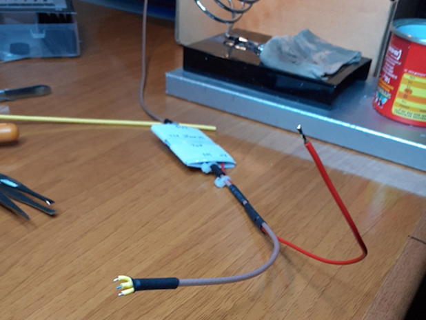
This is accessible through special contacts on the printed circuit called “CONNECTOR 1”.

In order not to disassemble the “CONNECTOR 1” printed circuit board, it was decided not to solder the pins of the “SPARE” RCA connector and the end of the IF output cable from IFace v.2 was terminated with two golden female pins recovered from a military connector VEAM AMPHENOL.

At this point the work is finished and from the rear of the radio the IF signal is conveniently available and ready to be sent to the external SDR receiver (in the photo it is visible in blue).


Again a big thank you to IZ4AQT Nicola for this beautiful work of documentation of his installation.

For more information on our IFace buffer interface click here.

To find out about all the radios on which the card can be installed click here.

We remind you that to buy the IFace you can use one of the following buttons.

ATTENTION: Although the installation of IFace 2 is not difficult, it is done at your own risk. TSP S.r.l. is not responsible for any damage, unwanted side effects or anything else.

IC-745 with SDR panadapter

Our buffer interface named IFace can be used to add an SDR panadapter to the Icom IC-745.

The operations to be carried out are very simple, it is sufficient to obtain from its wiring diagram the information on the points where the IF signal has to be taken. This radio uses several mixers and we are interested in the first IF frequency (this makes it easier to operate the panadapter). The IF frequency chosen is 70.4515 MHz and our SDR panadapter will be tuned to this. The following image shows the block diagram of the radio and where to get the IF signal.

The following image shows the portions of the schematic diagram of the IF UNIT where we can see the exact points where to sample the IF signal, the PTT+ and the power supply.

We now proceed to identify the exact points on the printed circuit board where to take the IF signal to be sent to the IFace. The following images show the sampling point for the IF signal and for the power supply for the buffer interface.

The use of PTT signal is required because RX and TX signals are not completely separated.

In order to buy an IFace use the buttons below.

ATTENTION: Though installing the IFace is not difficult, you do this at your own risk. TSP S.r.l. is not responsible for any damage, unwanted side-effects or whatever.

For more information, do not hesitate to write to us using the form below.
Have fun!

Please enable JavaScript in your browser to complete this form.
Name

Kenwood RZ-1 with SDR panadapter

Our buffer interface named IFace can be used to add an SDR panadapter to the Kenwood RZ-1.

The operations to be carried out are very simple, it is sufficient to obtain from its wiring diagram the information on the points where the IF signal has to be taken. This radio uses several mixers and we are interested in a common IF frequency among them (this makes it easier to operate the panadapter). The chosen IF frequency is 45.75 MHz and our SDR panadapter will be tuned to this. The following image shows the block diagram of the radio and where to get the IF signal.

The following image shows the portions of the schematic diagram of the IF UNIT where we can see the exact points where to sample the IF signal and the power supply.

We now proceed to identify the exact points on the printed circuit board where to take the IF signal to be sent to the IFace. The following images show the sampling point for the IF signal and for the power supply for the buffer interface.

The use of PTT signal is not required, it’s a receiver.

In order to buy an IFace use the buttons below.

ATTENTION: Though installing the IFace is not difficult, you do this at your own risk. TSP S.r.l. is not responsible for any damage, unwanted side-effects or whatever.

For more information, do not hesitate to write to us using the form below.
Have fun!

Please enable JavaScript in your browser to complete this form.
Name

Jackson with SDR panadapter

Our buffer interface named IFace can be used to add an SDR panadapter to the President Jackson.

The operations to be carried out are very simple, it is sufficient to obtain from its wiring diagram the information on the points where the IF signal has to be taken. This radio uses one mixer only for the receptio. The IF frequency is 10.7 MHz and our SDR panadapter will be tuned to this. The following image shows the block diagram of the radio and where to get the IF signal.

The following images show the portions of the schematic diagram of the IF UNIT where we can see the exact points where to sample the IF signal and the power supply.

We now proceed to identify the exact points on the printed circuit board where to take the IF signal to be sent to the IFace. The following images show the sampling point for the IF signal and for the power supply for the buffer interface.

The use of PTT signal is not required, RX and TX signals are separated.

In order to buy an IFace use the buttons below.

ATTENTION: Though installing the IFace is not difficult, you do this at your own risk. TSP S.r.l. is not responsible for any damage, unwanted side-effects or whatever.

For more information, do not hesitate to write to us using the form below.
Have fun!

Please enable JavaScript in your browser to complete this form.
Name

IC-7200 with SDR panadapter

Our buffer interface named IFace can be used to add an SDR panadapter to the Icom IC-7200.

The operations to be carried out are very simple, it is sufficient to obtain from its wiring diagram the information on the points where the IF signal has to be taken. This radio uses several mixers and we are interested in a common IF frequency among them (this makes it easier to operate the panadapter). The IF frequency chosen is 64.455 MHz and our SDR panadapter will be tuned to this. The following image shows the block diagram of the radio and where to get the IF signal.

The following image shows the portions of the schematic diagram of the IF UNIT where we can see the exact points where to sample the IF signal and the power supply.

We now proceed to identify the exact points on the printed circuit board where to take the IF signal to be sent to the IFace. The following images show the sampling point for the IF signal and for the power supply for the buffer interface.

The use of PTT signal is not required, RX and TX signals are separated.

In order to buy an IFace use the buttons below.

ATTENTION: Though installing the IFace is not difficult, you do this at your own risk. TSP S.r.l. is not responsible for any damage, unwanted side-effects or whatever.

For more information, do not hesitate to write to us using the form below.
Have fun!

Please enable JavaScript in your browser to complete this form.
Name

© TSP S.r.l. | VAT IT03137540542 | V.le Unità d'Italia 36, 06019 Umbertide, ITALY

NEWS July 18, 2024
A Telegram group is now available through which you can interact to get faster responses from other customers or, if necessary, from TSP Srl. Sign up for free by clicking here: Telegram TSP Customers. Please limit the use of contact forms to send generic requests, they have low reading priority because they are often used to send spam.

NOVITA' 18 Luglio 2024
E' da oggi disponibile un gruppo Telegram tramite il quale interagire per avere risposte più veloci da altri clienti o, in caso, da TSP Srl. Iscrivetevi gratuitamente facendo click qui: Telegram Clienti TSP. Per favore limitare l'utilizzo dei form di contatto per inviare richieste generiche, hanno bassa priorità di lettura perché spesso usati per inviare spam.
This is default text for notification bar