The operations to be carried out are very simple, it is sufficient to obtain from its wiring diagram the information on the points where the IF signal has to be taken. This radio uses several mixers, we are interested in the first of the reception chain as it gives us a broadband signal. The IF frequency is 64.455 MHz. The following image shows the block diagram of the radio and where to get the IF signal.
The following images show the portions of the schematic diagram of the RF UNIT where we can see the exact points where to sample the IF signal and the power supply.
We now proceed to identify the exact points on the printed circuit board where to take the IF signal to be sent to the IFace. The following images show the sampling point for the IF signal and for the power supply for the buffer interface.
The use of PTT signal is not required, RX and TX signals are separated.
In order to purchase an IFace use the buttons below.
ATTENTION: Though installing the IFace is not difficult, you do this at your own risk. TSP S.r.l. is not responsible for any damage, unwanted side-effects or whatever.
For more information, do not hesitate to write to us using the form below. Have fun!
The operations to be performed are very simple, it is sufficient to obtain from its wiring diagram the information on the points where to take the IF signals.
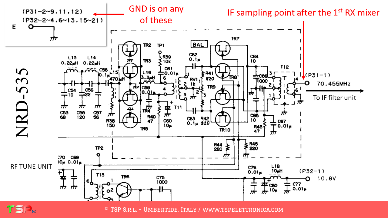
This radio uses different mixers. In particular, we will have to use the first one of the RX chain because we will have a wideband signal aroud the IF frequency (that is 70.455 MHz). The following images show the block diagram of the radio.
The following images show the portions of the schematic diagram of the RF TUNE and of the MOTHERBOARD where we can see the exact points where to sample the IF signal and the power supply.
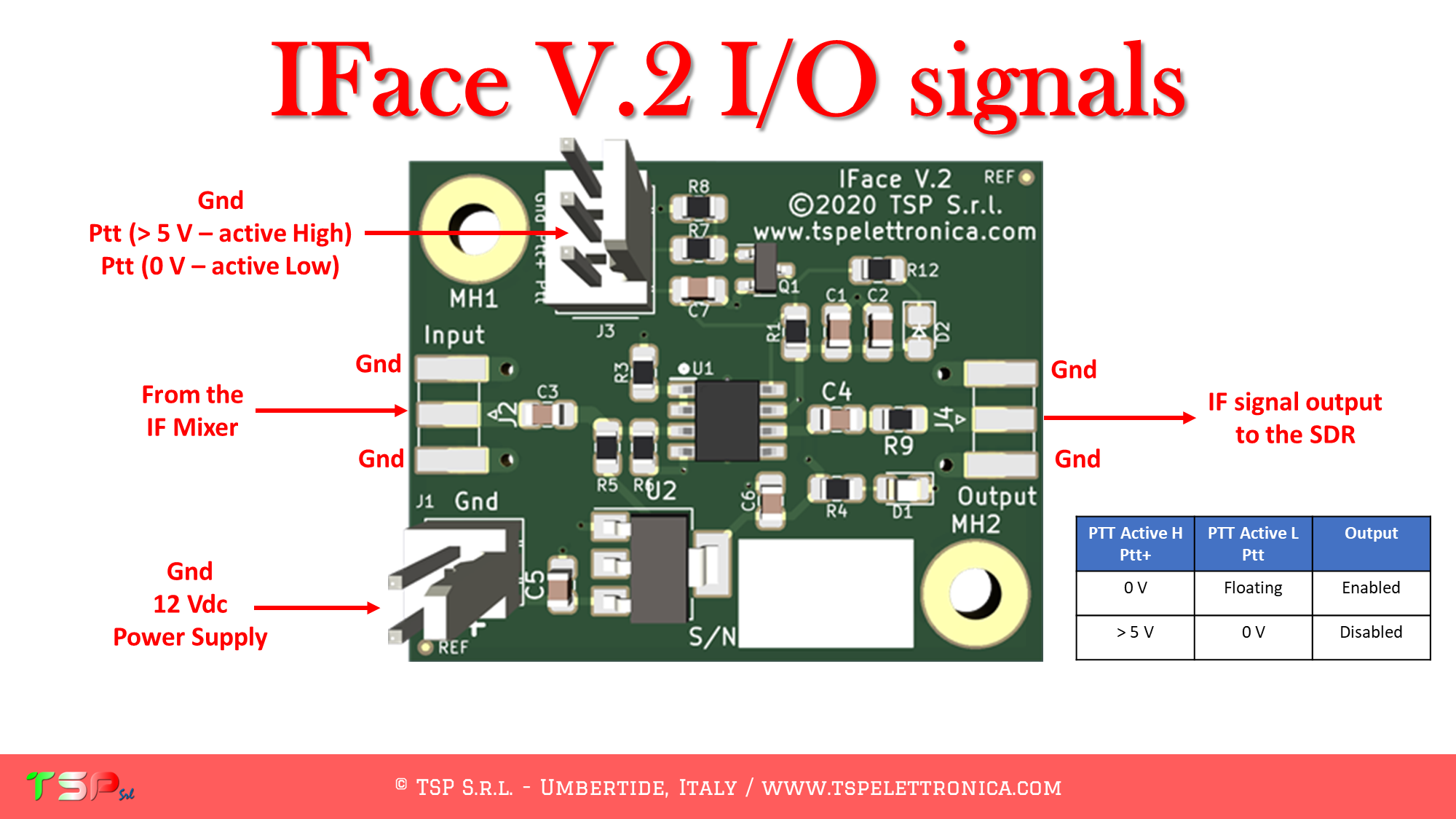
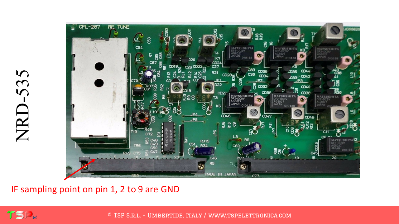
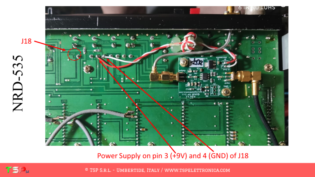
We now proceed to identify the exact points on the printed circuit board where to take the IF signal to be sent to the IFace. The following images show the sampling point for the IF signal and for the power supply for the buffer interface.
The use of PTT signal is not required, it’s a receiver!
In order to purchase an IFace use the buttons below.
ATTENTION: Though installing the IFace is not difficult, you do this at your own risk. TSP S.r.l. is not responsible for any damage, unwanted side-effects or whatever.
For more information, do not hesitate to write to us using the form below. Have fun!
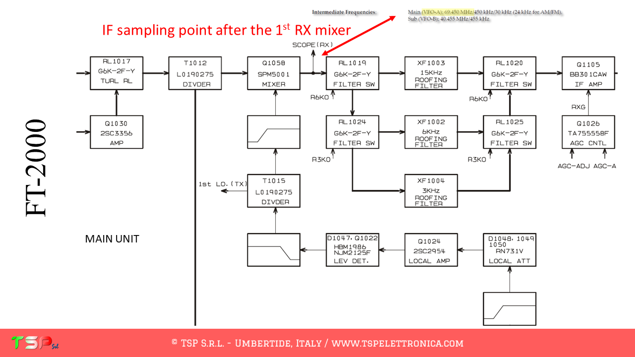
The operations to be carried out are very simple, it is sufficient to obtain from its wiring diagram the information on the points where the IF signal has to be taken. This radio uses several mixers, we are interested in the first of the reception chain as it gives us a broadband signal. The IF frequency is 69.450 MHz. The following image shows the block diagram of the radio and where to get the IF signal.
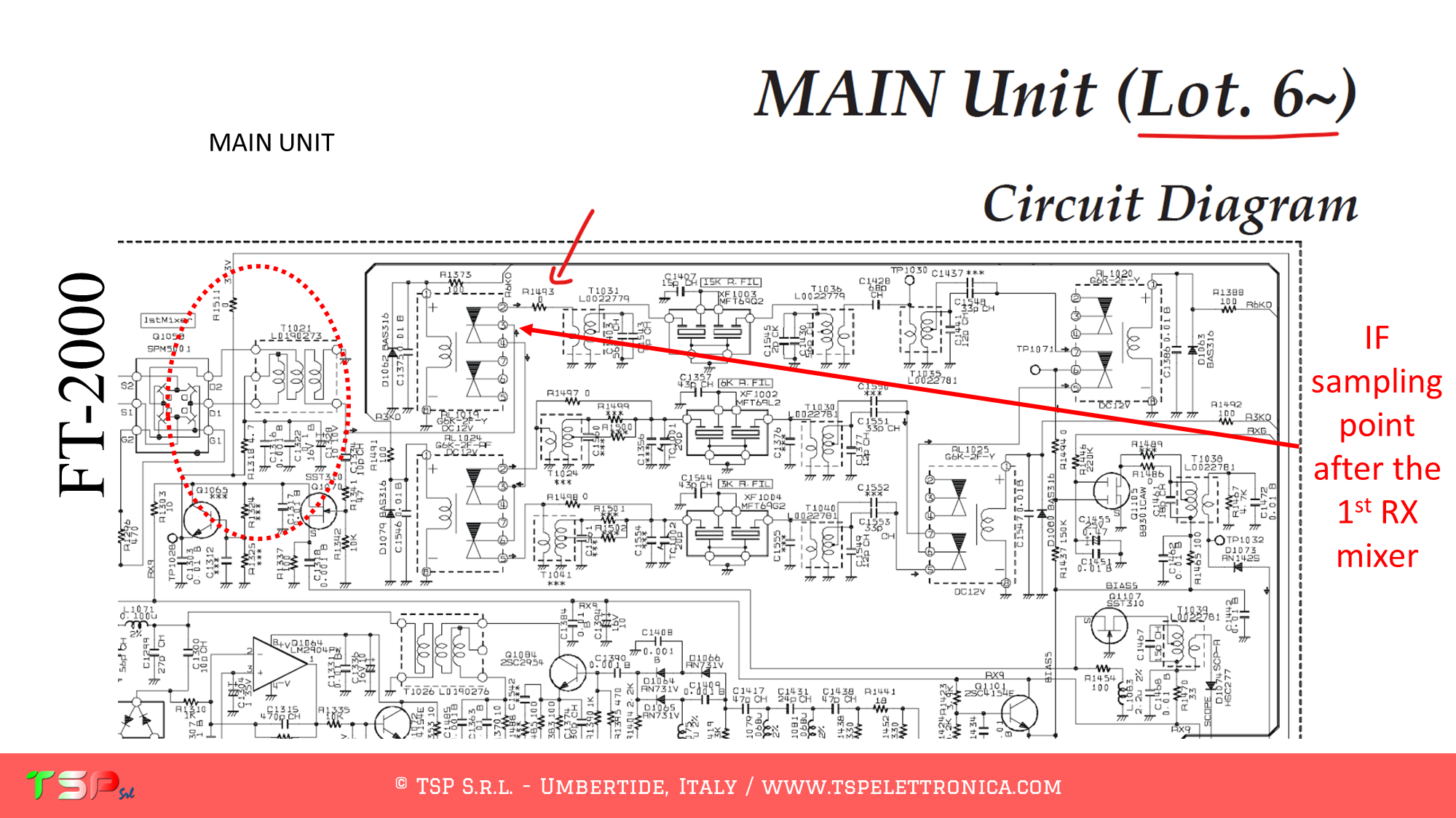
The following images show the portions of the schematic diagram of the MAIN UNIT where we can see the exact points where to sample the IF signal and the power supply.
In the years, Yaesu produced several versions of the MAIN Unit. They changed the position of the resistor R1493, but the sampling point remains the same on the common contact of RL1019.
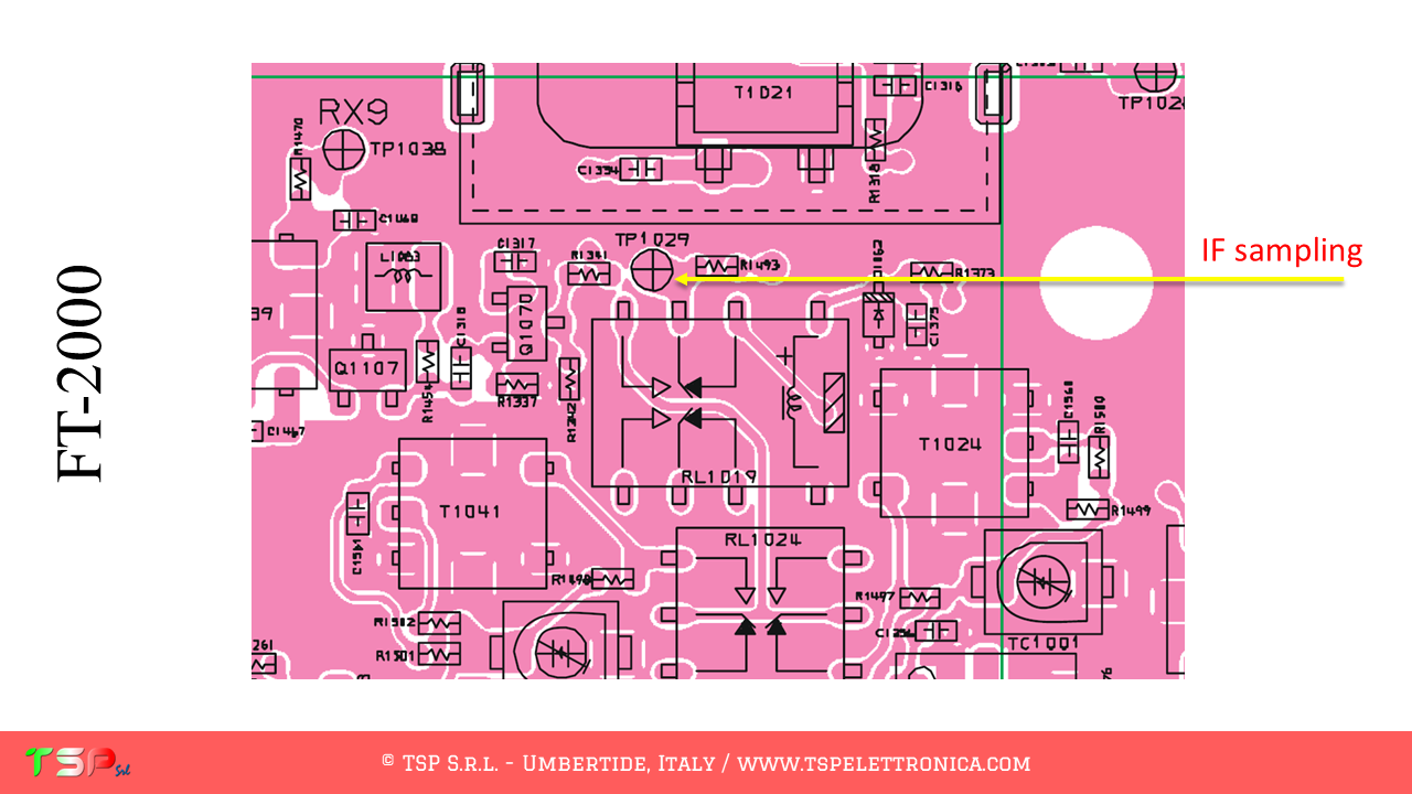
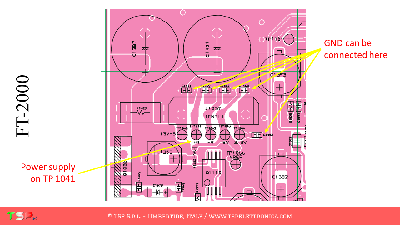
We now proceed to identify the exact points on the printed circuit board where to take the IF signal to be sent to the IFace. The following images show the sampling point for the IF signal and for the power supply for the buffer interface.
The use of PTT signal is not required, RX and TX signals are separated.
In order to purchase an IFace use the buttons below.
ATTENTION: Though installing the IFace is not difficult, you do this at your own risk. TSP S.r.l. is not responsible for any damage, unwanted side-effects or whatever.
For more information, do not hesitate to write to us using the form below. Have fun!
The operations to be performed are very simple, it is sufficient to obtain from its wiring diagram the information on the points where to take the IF signals.
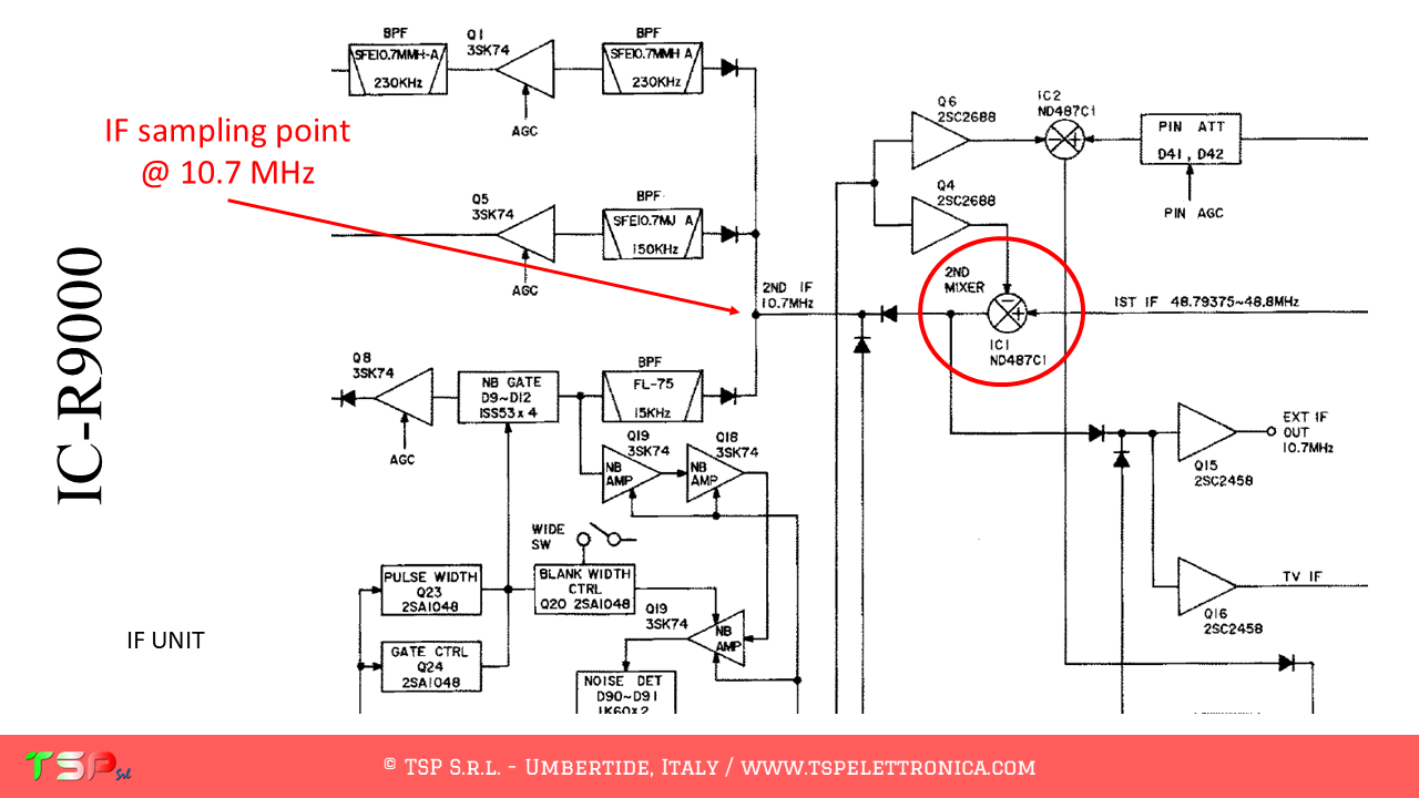
This radio uses different mixers. In particular, we will have to use the second one of the RX chain because the IF frequency will be the same for all the bands, 10.7 MHz. The following images show the block diagram of the radio.
The following two images show the portions of the schematic diagram of the IF UNIT where we can see the exact points where to sample the IF signal and the power supply.
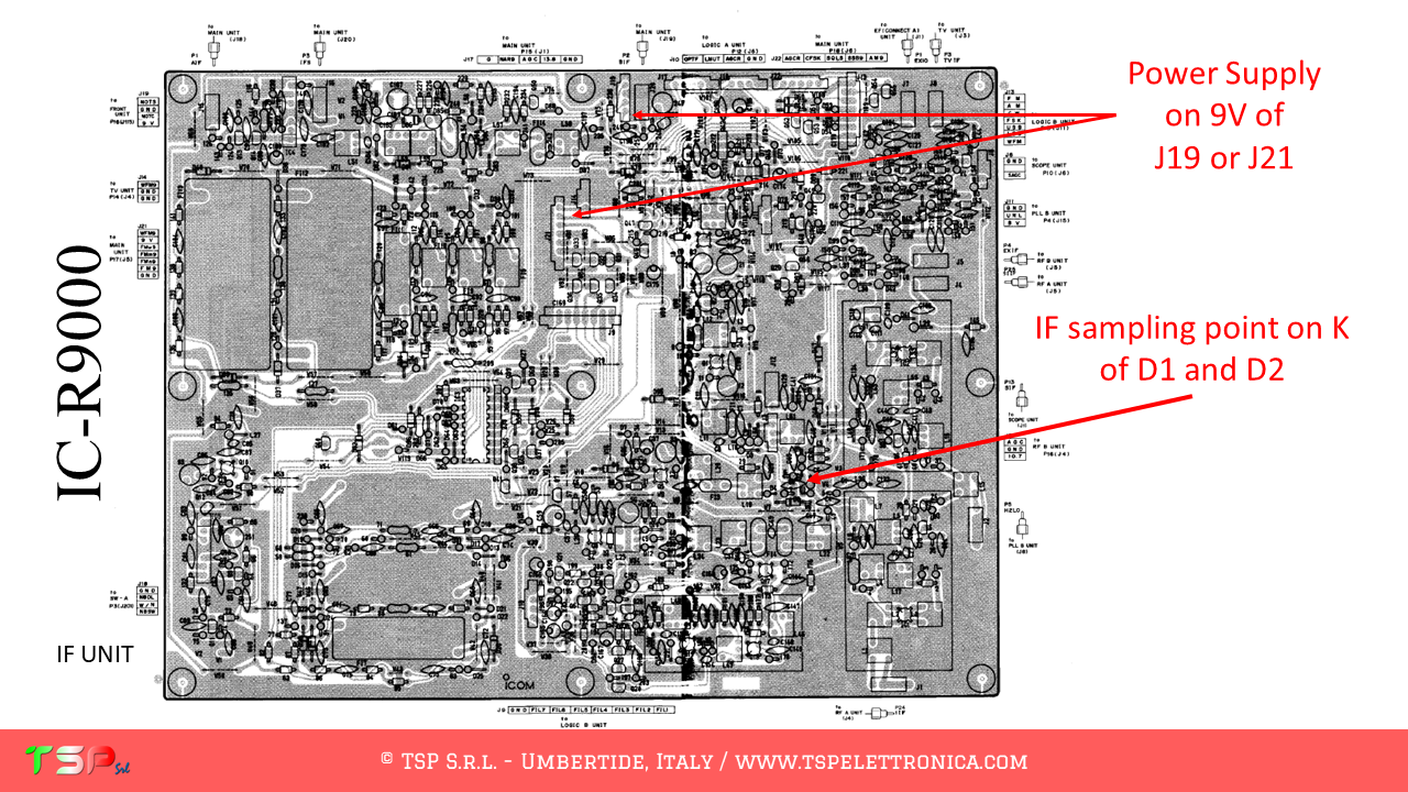
We now proceed to identify the exact points on the printed circuit board where to take the IF signal to be sent to the IFace. The following images show the sampling point for the IF signal and for the power supply for the buffer interface.
The use of PTT signal is not required, it’s a receiver!
In order to purchase an IFace use the buttons below.
ATTENTION: Though installing the IFace is not difficult, you do this at your own risk. TSP S.r.l. is not responsible for any damage, unwanted side-effects or whatever.
For more information, do not hesitate to write to us using the form below. Have fun!
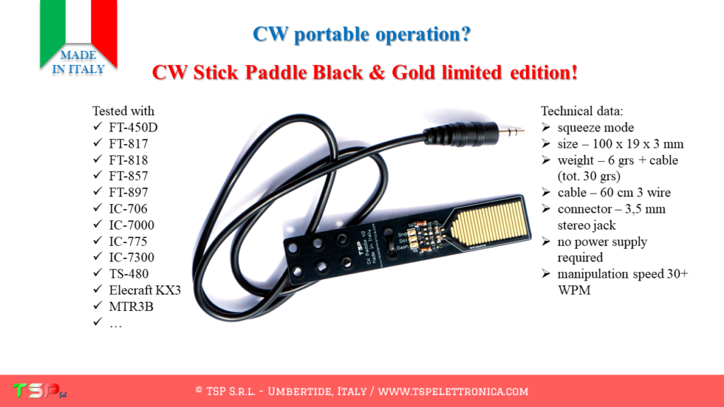
If you still have doubts about the validity of our CW Stick Paddle, read below the answers to the most frequent questions we have received so far.
Q. What is the difference between the “standard” version and the “Black & Gold Limited Edition” version?
A. The two keys are identical in terms of circuitry, that is, the difference is the finish, the first green, the second black, and the “touch” metallization, the first tin-plated, the second real gold-plated.
Q. Is it a resistive or capacitive key?
A. It is a resistive key, it works by exploiting the surface resistance of the skin. Extremely dry or hardened skins have a very high surface resistance and may not work well: in this case, moisturize it.
Q. How fast can you use it?
A. It depends on your skills, but in general, in the configuration sold, it works well at least up to 30 WPM or more. If you want to go much faster, above 40 WPM, you need to replace two resistors (currently 10 MOhm) with lower values.
D. Does it need for power?
R. No! The power supply is obtained directly from the “dash” and “dot” signals, there are no batteries that discharge.
Q. Does it work with all radios?
A. Yes, but it depends on the voltages on the “dot” and “dash” lines. In general, 5 V or voltages close to this value must be found on the wires and transmission must take place by grounding (GND) one of these lines.
For any other questions, use the form below. Thanks.
If you still have doubts about the validity of our IFace (click here), read below the answers to the most frequent questions we have received so far.
Q. What are the differences between IFace and IFace 2?
A. IFace and IFace 2 are 100% compatible. IFace 2 is an optimized version of IFace and is smaller. IFace 2 replaces the first version (which will no longer be sold).
Q. Can I continue to use the RTX without an SDR receiver connected to the IFace?
A. Obviously yes, the IFace does not influence the functioning of the radio in the least, it only serves to take a copy of the IF signal so that it can be sent to the external SDR receiver.
Q. What bandwidth can I see with the panadapter?
R. It depends, but above all, it does not depend on the IFace. It depends on the external SDR receiver you are going to use. For example, a classic RTL-SDR without decimation can typically reach 1 MHz bandwidth. An RSP1 can reach 10 MHz. If decimation is used, as we recommend, the band typically displayed is around 200 kHz (however more than enough for most applications).
Q. Is PTT necessary?
R. It depends, not always. It depends on the type of radio, in particular how the reception circuit is made. For example, if it uses part of the transmitter circuits then the answer is yes, otherwise if they are clearly separated the answer is no.
Q. What do “PTT Active High” and “PTT Active Low” mean?
A. Digital signals, such as the PTT signal, can be active high or active low. In the case of “active high” the PTT signal goes from 0 V to a higher value, typically 5 V or more. In the case of “active low,” the PTT signal goes from 5 or more volts to 0 V. Generally inside the radios the signal is “active high”. The “active low” signal is typical of an open-collector or open-drain transistor configuration.
Q. My radio does not have the CAT interface: at what frequency should the external SDR receiver be tuned?
A. In this case, if you do not use synchronization between computer and radio via CAT interface, the frequency to be used to receive correctly through the SDR panadapter is that of the IF to which the IFace is connected. Refer to the specific documentation for the installation of our interface.
Q. Can I use the CAT cable to change the frequency regardless of the VFO knob on the RTX or the software and have the same frequency value on both the SDR software and the radio?
A. Obviously yes, that’s what we recommend doing. If you use CAT to synchronize the radio and the SDR software, you will have full control of it directly from the computer screen.
Q. Where do I connect the coaxial cable braid to the IFace?
A. It can be connected to one of the holes on the PCB or, if coaxial connectors are not used, to one of the pads where the external part of the connector should be welded.
Q. I have an RTX that already has an IF output. If I connect my SDR there, would I get the same performance as if I used the IFace?
A. No. Generally, with IFace, the performances are better because we can connect it directly after the first IF mixer and before the roofing filter. This results in a band displayed on the screen that is much wider than that displayed on the radio’s IF output.
Q. What do you need besides your IFace card to have a complete panadapter?
A. In general, you need an A / D converter for RF signals, also called an SDR receiver (ex. RTL-SDR or SDRplay) and a special program for the computer (HDSDR, SDR Console, SDR #, SDRuno etc.). That’s it.
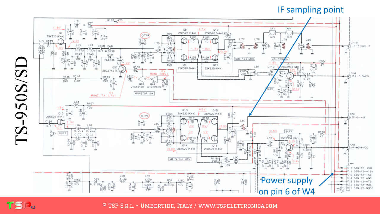
The operations to be performed are very simple, it is sufficient to obtain from its wiring diagram the information on the points where to take the IF signals.
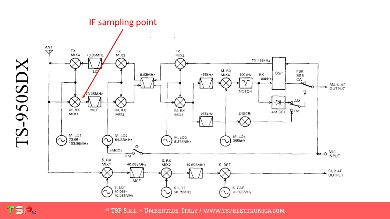
This radio, in fact, uses different mixers. In particular, we will have to use the first of the RX chain. The following images show the block diagram of the radio. For the TS-950S/SD the first IF is at 73.05 MHz.
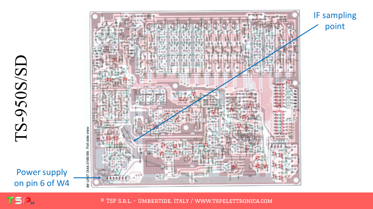
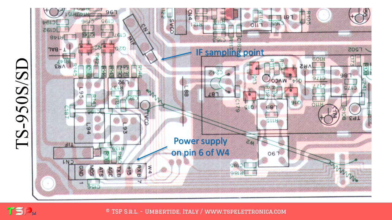
We now proceed to identify the exact points on the printed circuit board where to take the IF signal to be sent to the IFace. The following images show the sampling point for the IF signal and for the power supply for the buffer interface.
The use of PTT signal is not required.
In order to purchase an IFace use the buttons below.
ATTENTION: Though installing the IFace is not difficult, you do this at your own risk. TSP S.r.l. is not responsible for any damage, unwanted side-effects or whatever.
For more information, do not hesitate to write to us using the form below. Have fun!
The operations to be performed are very simple, it is sufficient to obtain from its wiring diagram the information on the points where to take the IF signals.
This radio, in fact, uses different mixers. In particular, we will have to use the first of the RX chain. The following images show the block diagram of the radio. For the IC-7000 the first IF is at 124.487 MHz.
We now proceed to identify the exact points on the printed circuit board where to take the IF signal to be sent to the IFace. The following images show the sampling point for the IF signal and for the power supply for the buffer interface.
The use of PTT signal is not required.
In order to purchase an IFace use the buttons below.
ATTENTION: Though installing the IFace is not difficult, you do this at your own risk. TSP S.r.l. is not responsible for any damage, unwanted side-effects or whatever.
For more information, do not hesitate to write to us using the form below. Have fun!
The operations to be performed are very simple, it is sufficient to obtain from its wiring diagram the information on the points where to take the IF signals.
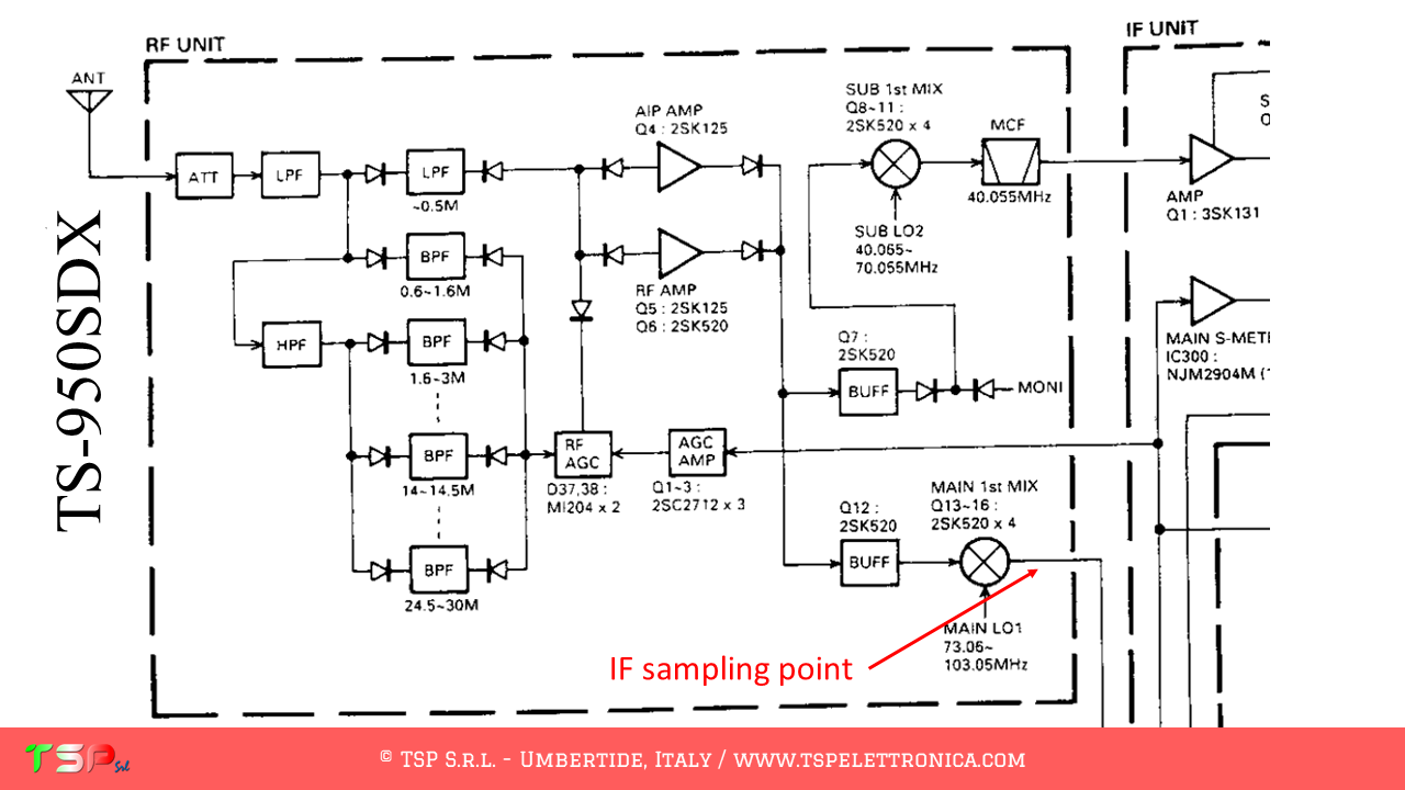
This radio, in fact, uses different mixers. In particular, we will have to use the first of the RX chain. The following images show the block diagram of the radio. For the TS-950SDX the first IF is at 73.05 MHz.
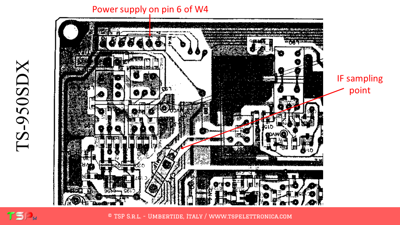
We now proceed to identify the exact points on the printed circuit board where to take the IF signal to be sent to the IFace. The following images show the sampling point for the IF signal and for the power supply for the buffer interface.
The use of PTT signal is not required.
In order to purchase an IFace use the buttons below.
ATTENTION: Though installing the IFace is not difficult, you do this at your own risk. TSP S.r.l. is not responsible for any damage, unwanted side-effects or whatever.
For more information, do not hesitate to write to us using the form below. Have fun!
In addition to the instructions below, we also have a great testimonial. It was sent to us by IZ4QAT Nicola, and a warm thanks goes to him. You can find it here: IC-781 SDR by IZ4AQT Nicola.
The operations to be performed are very simple, it is sufficient to obtain from its wiring diagram the information on the points where to take the IF signals.
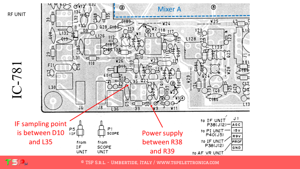
This radio, in fact, uses different mixers. In particular, we will have to use the first of the RX chain. The following images show the block diagram of the radio. For the IC-781 the first IF is shown in the small table in the following image.
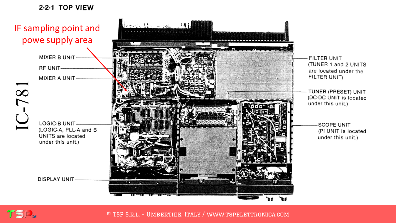
We now proceed to identify the exact points on the printed circuit board where to take the IF signal to be sent to the IFace. The following images show the sampling point for the IF signal and for the power supply for the buffer interface.
In order to purchase an IFace use the button below.
ATTENTION: Though installing the IFace is not difficult, you do this at your own risk. TSP S.r.l. is not responsible for any damage, unwanted side-effects or whatever.
For more information, do not hesitate to write to us using the form below. Have fun!
This website uses cookies to improve your experience. We'll assume you're ok with this, but you can opt-out if you wish.AcceptRead More
Privacy & Cookies Policy
Privacy Overview
This website uses cookies to improve your experience while you navigate through the website. Out of these, the cookies that are categorized as necessary are stored on your browser as they are essential for the working of basic functionalities of the website. We also use third-party cookies that help us analyze and understand how you use this website. These cookies will be stored in your browser only with your consent. You also have the option to opt-out of these cookies. But opting out of some of these cookies may affect your browsing experience.
Necessary cookies are absolutely essential for the website to function properly. This category only includes cookies that ensures basic functionalities and security features of the website. These cookies do not store any personal information.
Any cookies that may not be particularly necessary for the website to function and is used specifically to collect user personal data via analytics, ads, other embedded contents are termed as non-necessary cookies. It is mandatory to procure user consent prior to running these cookies on your website.