Installing IFace inside the TS-2000 – all bands

In two previous articles we have seen how to install the IFace card inside the Kenwood TS-2000 to obtain the IF signal of the HF and 50 MHz bands and of the VHF and UHF bands to be sent to an external SDR. Now let’s see how to get another single IF signal for all bands, including 23cm (1.2 GHz). Installation is very easy.

The result you can obtain is well shown in the following video.

The TS-2000, like other radios, has a fairly complex configuration and uses different intermediate frequencies depending on the band on which you are operating. There is the possibility of taking an IF signal at a single frequency (10,695 MHz) valid for all bands. This involves a reduction in the width of the displayable spectrum as the IF signal will have passed through some IF band filters. In any case, the one described here is the sequence of operations to be performed to obtain a bandwidth sufficient to create a panoramic receiver around the IF frequency relating to all the bands on which the radio can operate.

However, the displayable spectrum depends on the sampling frequency of the SDR receiver, not on IFace.

The point where to take the IF signal can be identified more precisely through the wiring diagram as shown in the following images. The electronic card of interest is the one called TX-RX UNIT and the signal can be taken among R111, C166 and C167.

Now we have to look for where to take the power supply: power can be taken from the CN 29 connector, signal 14S or 8A.

The points on the PCB where to take the signals are shown below.

PTT: for the TS-2000 it is not required because the reception circuit is automatically muted during transmission.

You can by IFace 2 simply making click on the buttons below.

ATTENTION: Though installing the IFace is not difficult, you do this at your own risk. TSP S.r.l. is not responsible for any damage, unwanted side-effects or whatever.

For more information do not hesitate to write us.
Have fun!

Panadapter SDR for the Galaxy DX 959

These are the instructions to install the IFace interface inside of the ICOM IC-736 / 738 in order to add an SDR panadapter to the radio. The installation is very easy.
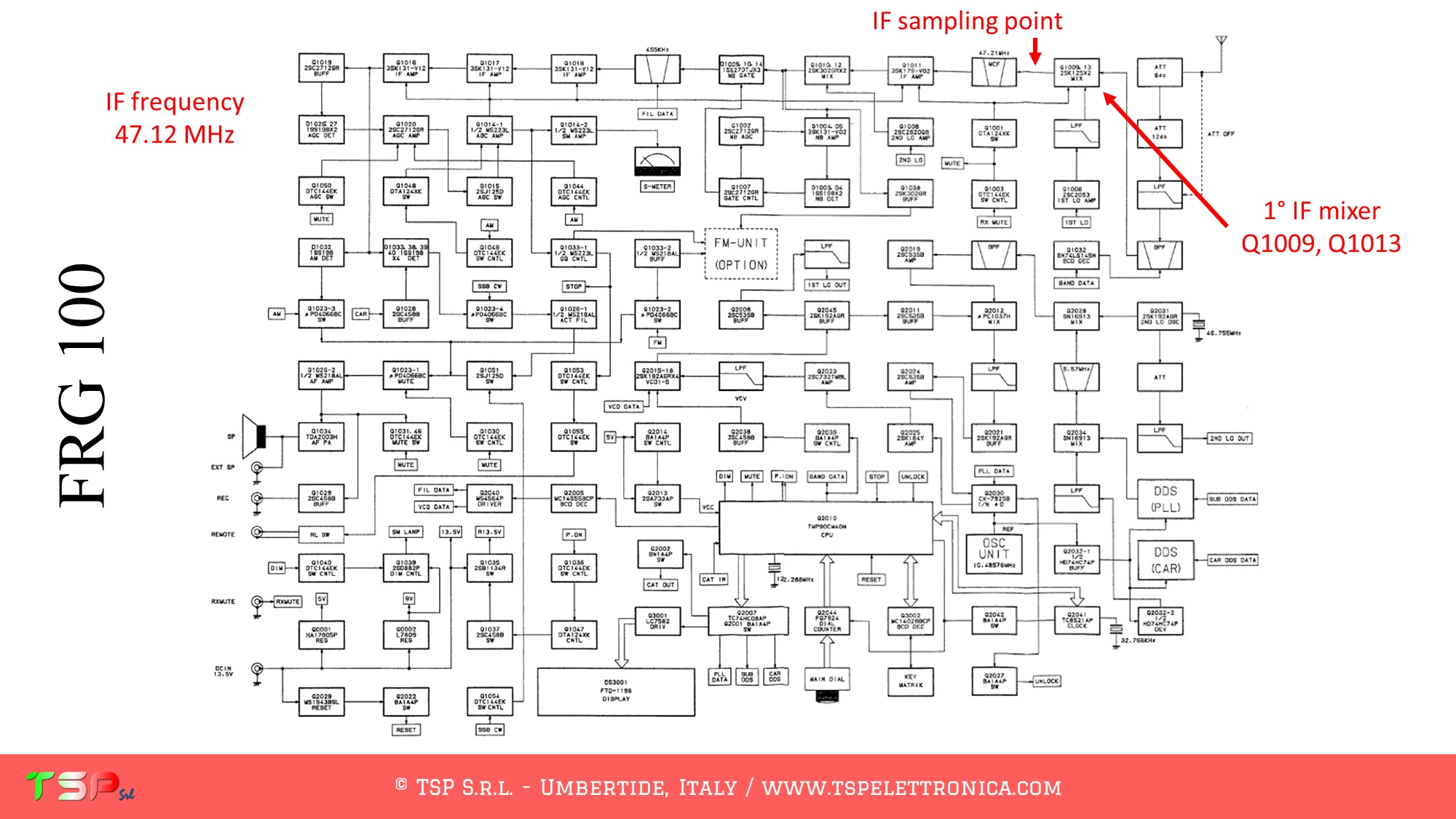
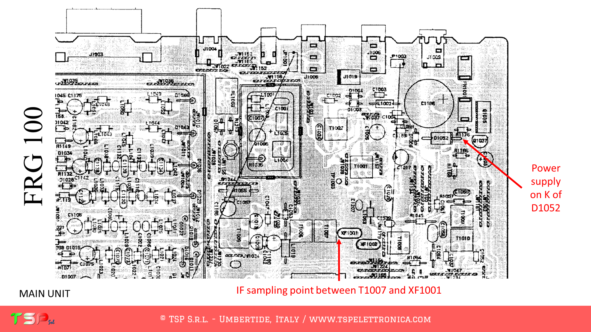
After removing the cover, locate the electronic board called “MAIN UNIT”: the signal we are interested in are on this board. The SDR receiver will be tuned on 10.7 MHz.

Refer to the following image to identify in the wiring diagram the points where to weld the cables for the IF, the power supply and the PTT. Several points have been highlighted where you can take the power supply, choose the one that best suits the installation.

Refer to the following image to identify the points on the PCB where to weld the various connecting cables.

In order to buy an IFace please use the following buttons.

Paypal

ATTENTION: Though installing the IFace is not difficult, you do this at your own risk. TSP S.r.l. is not responsible for any damage, unwanted side-effects or whatever.

For more information do not hesitate to write us.
Have fun!

Panadapter SDR for the IC-736 / 738

These are the instructions to install the IFace interface inside of the ICOM IC-736 / 738 in order to add an SDR panadapter to the radio. The installation is very easy.

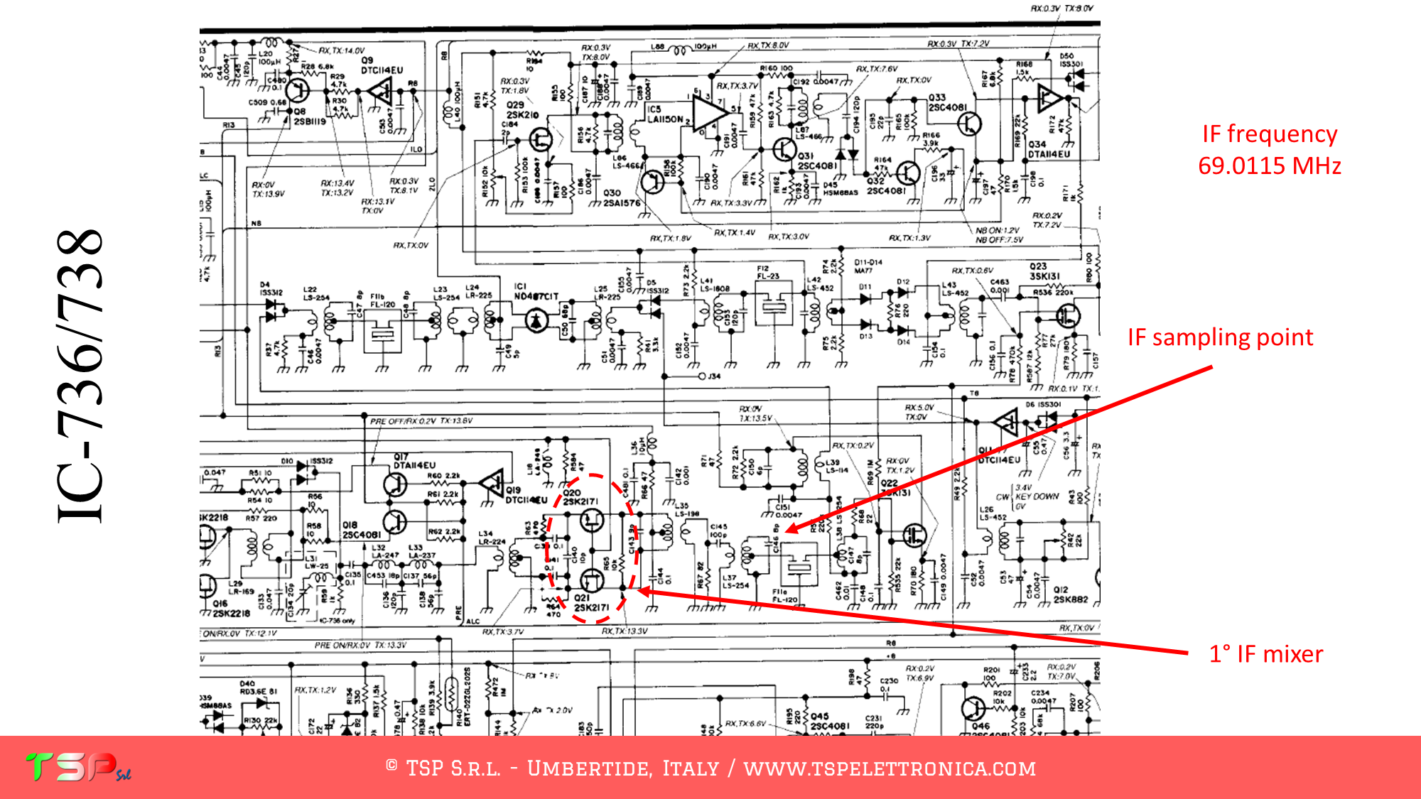
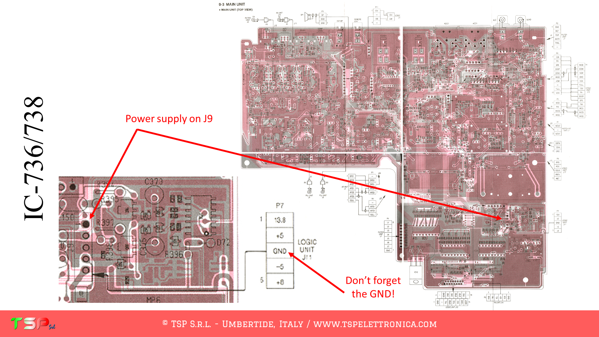
After removing the cover, locate the electronic board called “MAIN UNIT”: the signal we are interested in are on this board. The SDR receiver will be tuned on 69.0115 MHz.

Refer to the following image of the wiring diagram to identify the points where you can weld the cables for the IF and the power supply. The PTT+ is not required, the signal paths for the RX and the TX are mostly separated.

Refer to the following image to identify the points on the PCB where to weld the various connecting cables.

In order to buy an IFace please use the following buttons.

Paypal

ATTENTION: Though installing the IFace is not difficult, you do this at your own risk. TSP S.r.l. is not responsible for any damage, unwanted side-effects or whatever.

For more information do not hesitate to write us.
Have fun!
Panadapter SDR for the FT-757GX

These are the instructions to install the IFace interface inside of the Yaesu FT-757GX in order to add an SDR panadapter to the radio. The installation is very easy.

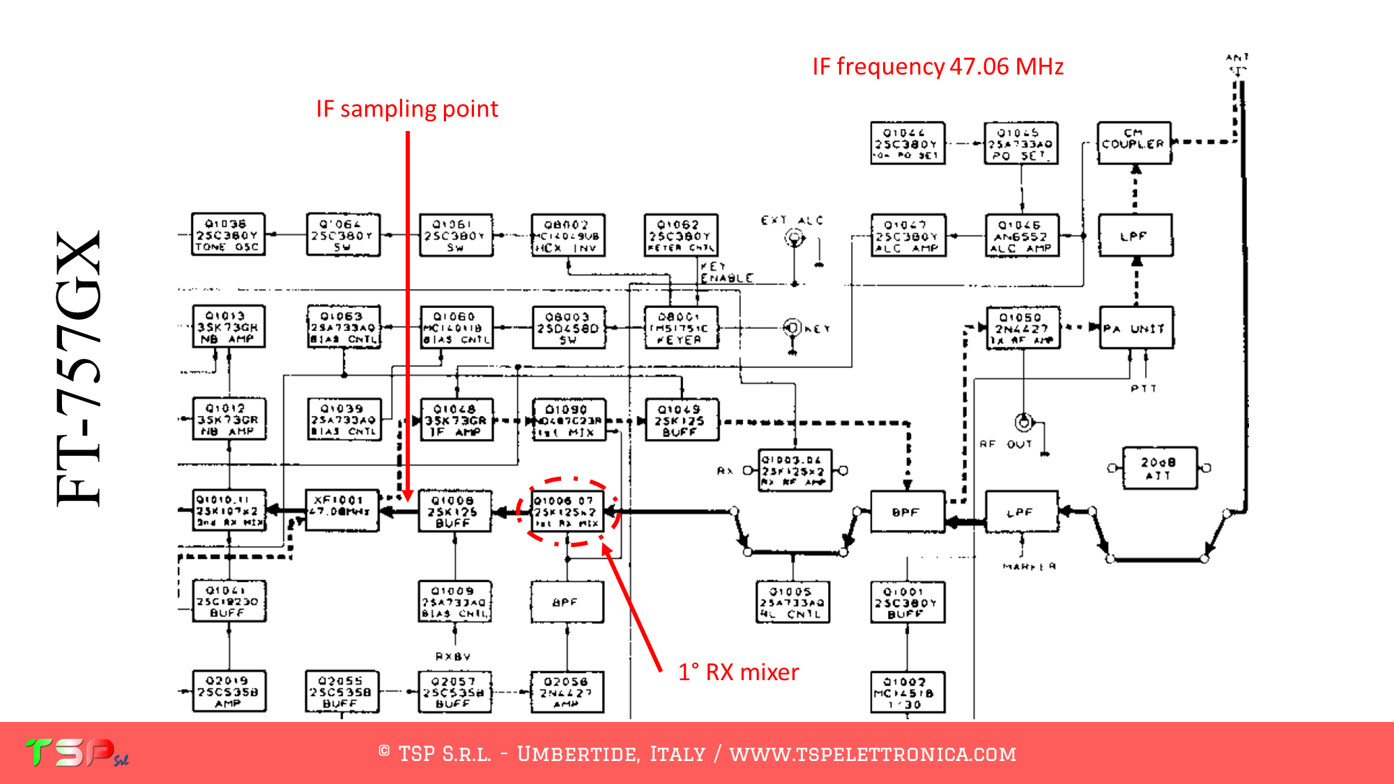
After removing the cover, locate the electronic board called “RF UNIT”: the signal we are interested in are on this board.

Refer to the following image of the wiring diagram to identify the points where you can weld the cables for the IF and the power supply. The PTT+ is required, the signal paths for the RX and the TX are not completeley separated.

Refer to the following image to identify the points on the PCB where to weld the various connecting cables.

In order to buy an IFace please use the following buttons.

Paypal

ATTENTION: Though installing the IFace is not difficult, you do this at your own risk. TSP S.r.l. is not responsible for any damage, unwanted side-effects or whatever.

For more information do not hesitate to write us.
Have fun!

Panadapter SDR for the FT-780R

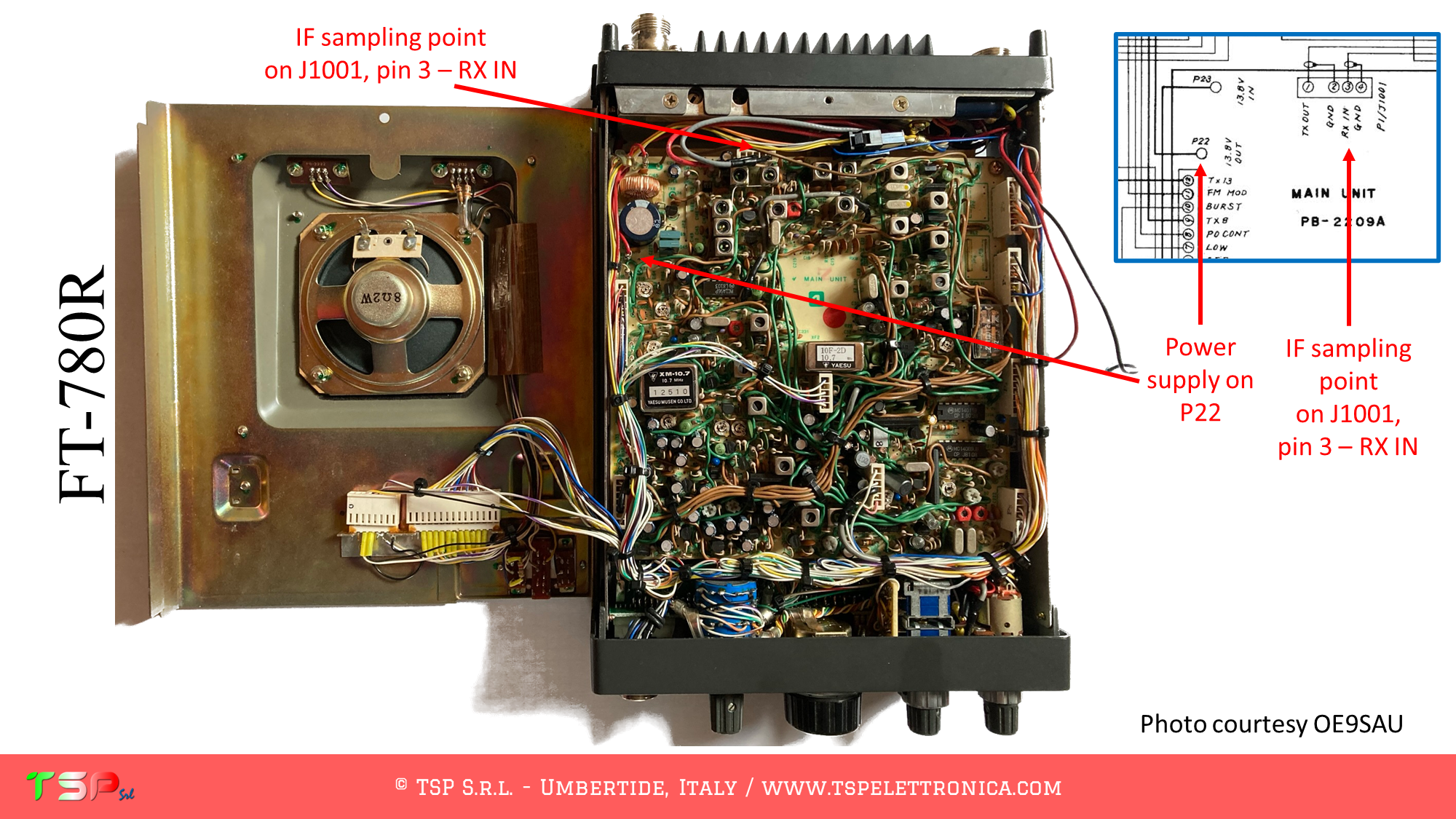
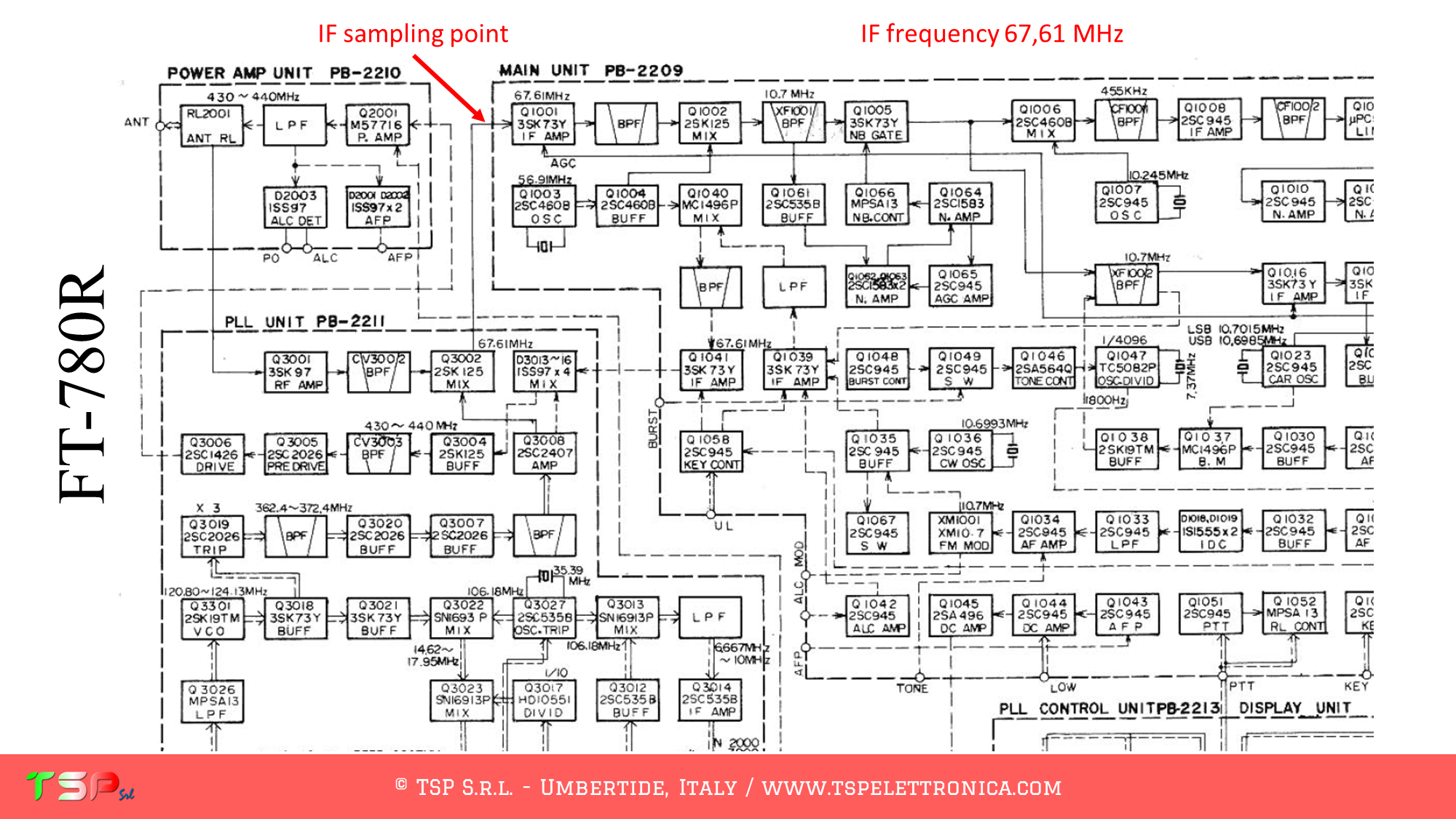
These are the instructions to install the IFace interface inside of the Yaesu FT-780R in order to add an SDR panadapter to the radio. The installation is very easy.

IFace 2

After removing the cover, locate the electronic board called “MAIN UNIT”: the signal we are interested in are on this board.

Refer to the following image of the wiring diagram to identify the points where you can weld the cables for the IF and the power supply. The PTT is not required, the signal paths are different for the RX and the TX.

Refer to the following image to identify the points on the PCB where to weld the various connecting cables.

In order to buy an IFace please use the following buttons.

Paypal

ATTENTION: Though installing the IFace is not difficult, you do this at your own risk. TSP S.r.l. is not responsible for any damage, unwanted side-effects or whatever.

For more information do not hesitate to write us.
Have fun!
Panadapter SDR for the FT-480R

These are the instructions to install the IFace interface inside of the Yaesu FT-480R in order to add an SDR panadapter to the radio. The installation is very easy.

IFace 2

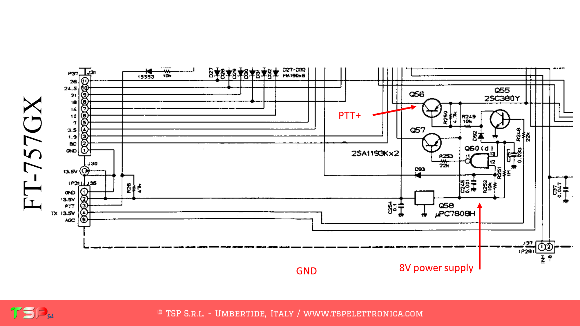
After removing the cover, locate the electronic board called “MAIN UNIT”: the signal we are interested in are on this board.

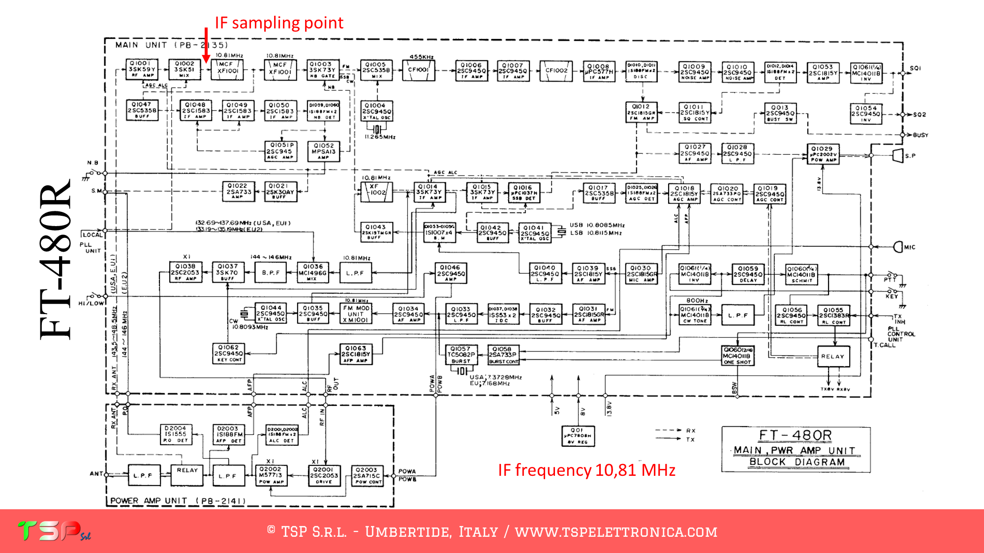
Refer to the following image of the wiring diagram to identify the points where you can weld the cables for the IF and the power supply. The PTT is not required, the signal paths are different for the RX and the TX.

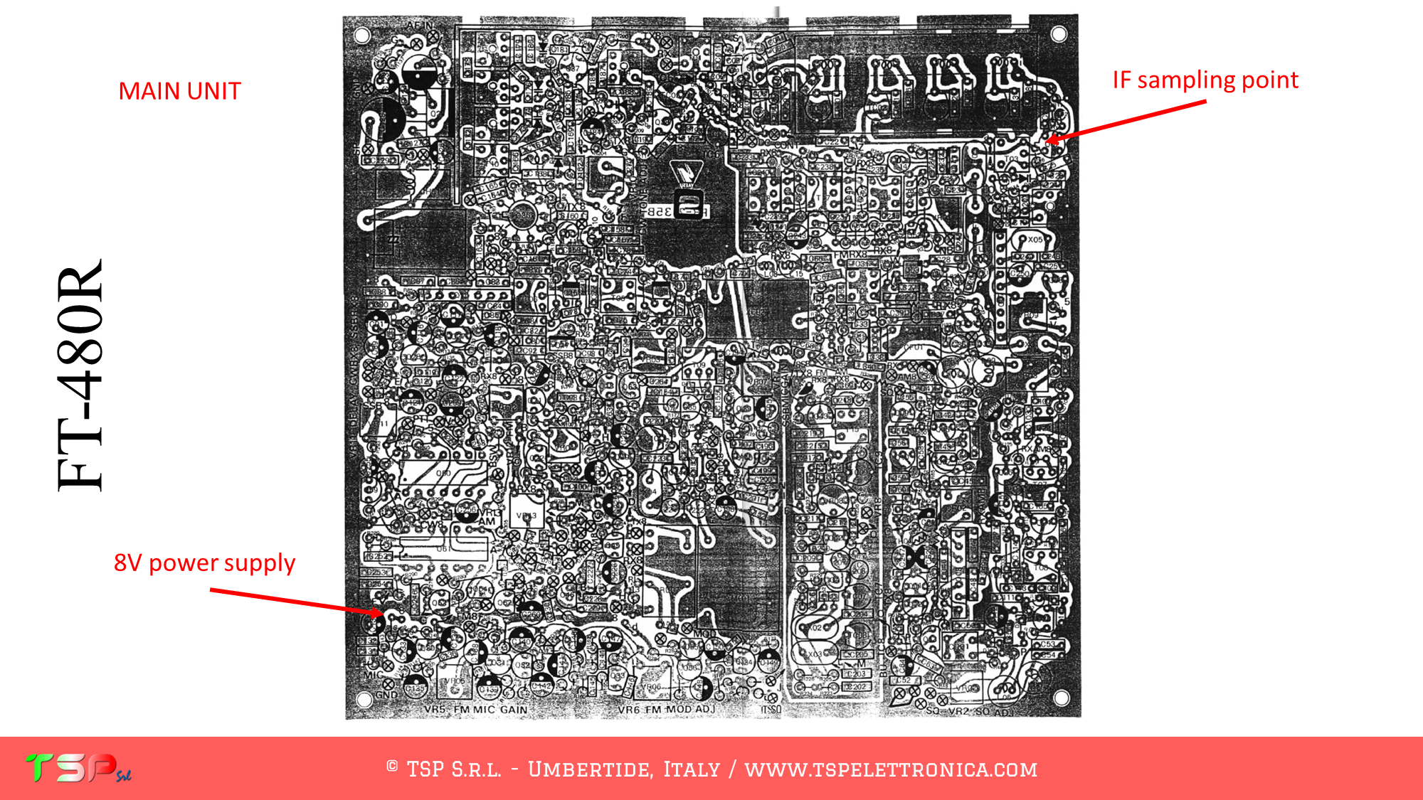
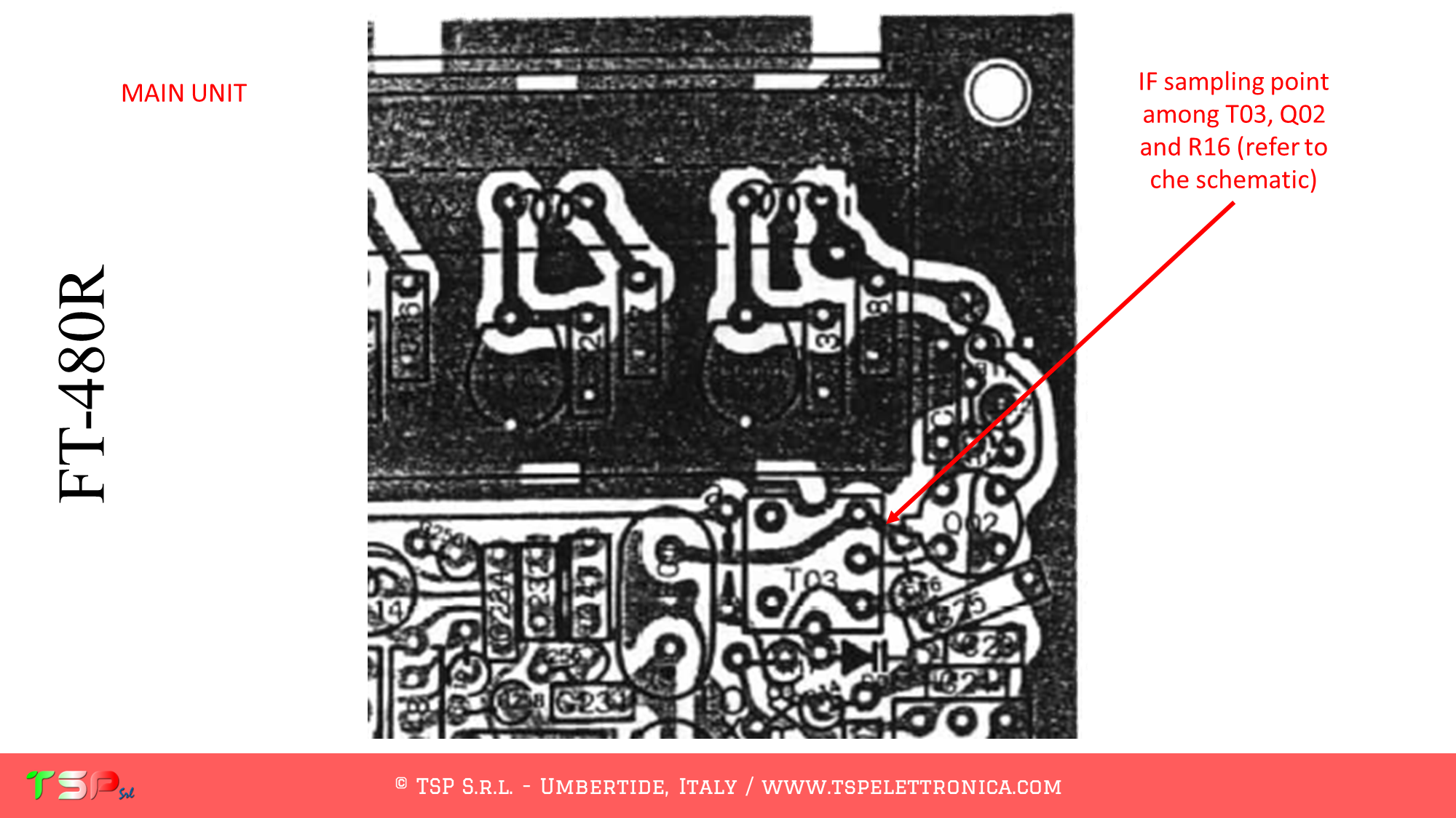
Refer to the following image to identify the points on the PCB where to weld the various connecting cables.

In order to buy an IFace please use the following buttons.

Paypal

ATTENTION: Though installing the IFace is not difficult, you do this at your own risk. TSP S.r.l. is not responsible for any damage, unwanted side-effects or whatever.

For more information do not hesitate to write us.
Have fun!

Panadapter SDR for the R-2000

These are the instructions to install the IFace interface inside of the Kenwood R-2000 in order to add an SDR panadapter to the radio. The installation is very easy.

IFace 2

After removing the cover, locate the electronic board called “RX Unit”: the signal we are interested in are on this board.

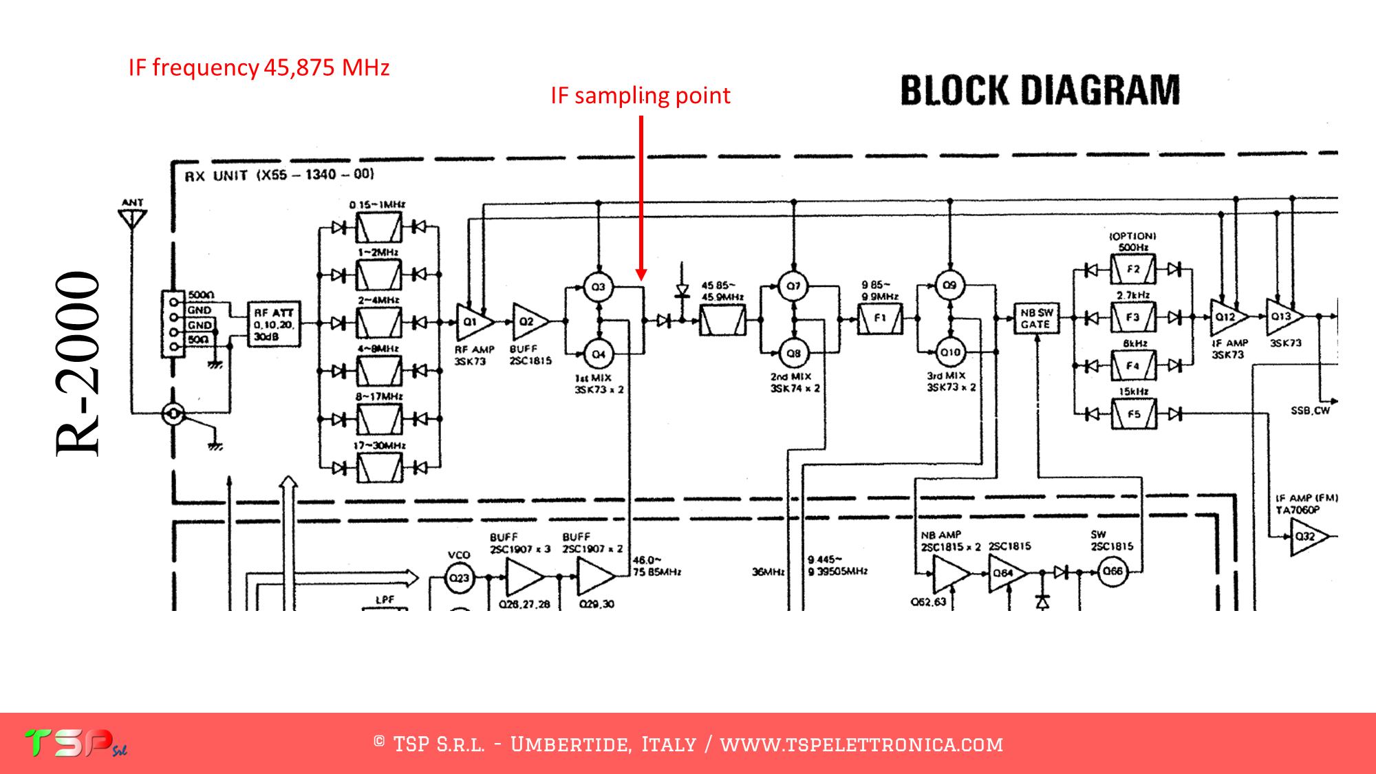
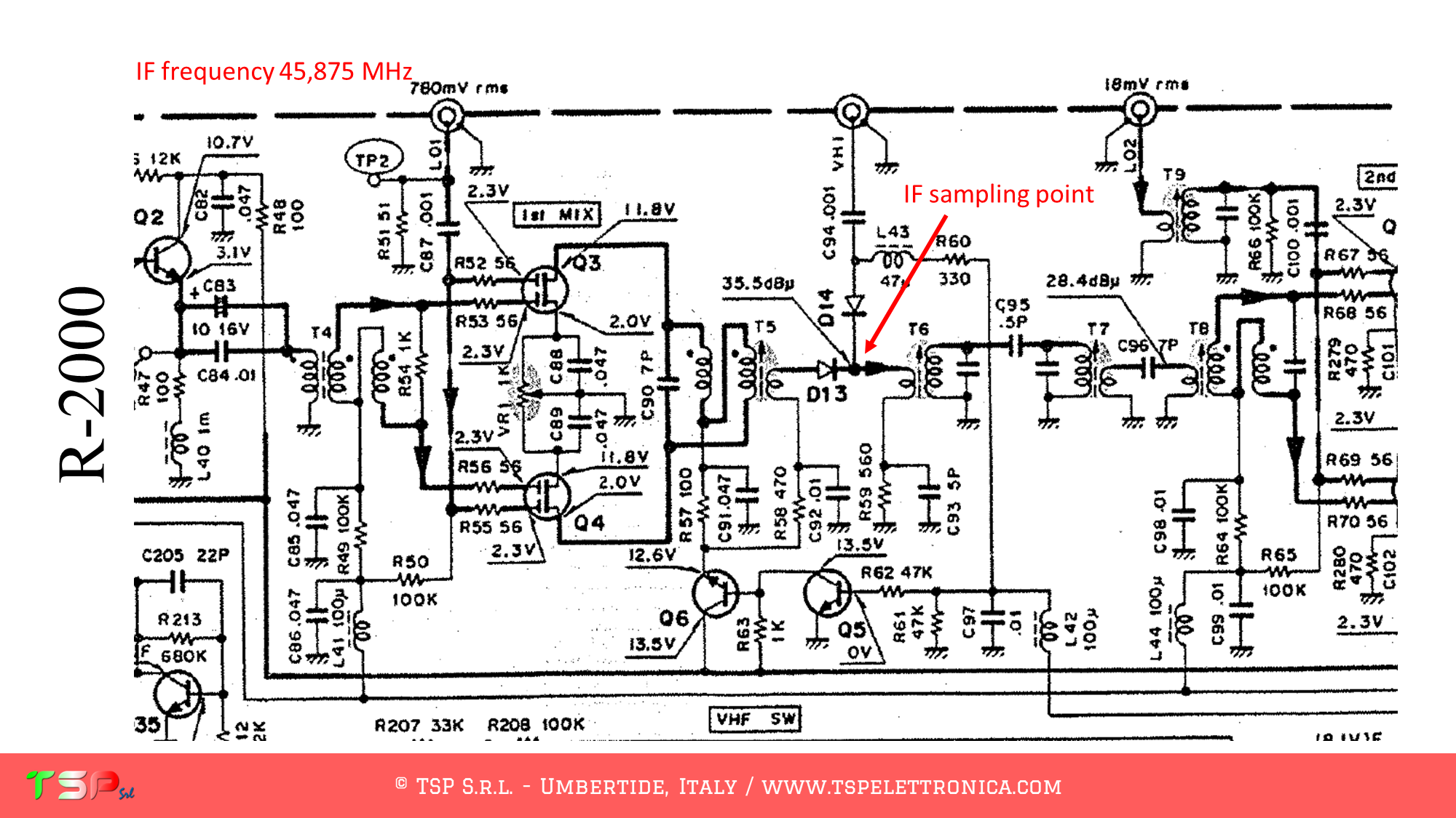
Refer to the following images of the wiring diagram to identify the points where you can weld the cables for the IF and the power supply. The PTT is not required, this is a receiver.

Refer to the following image to identify the points on the PCB where to weld the various connecting cables.

In order to buy an IFace please use the following buttons.

Paypal

ATTENTION: Though installing the IFace is not difficult, you do this at your own risk. TSP S.r.l. is not responsible for any damage, unwanted side-effects or whatever.

For more information do not hesitate to write us.
Have fun!
PCB: la larghezza delle piste

Sono molti i fattori che influenzano la larghezza delle piste quando si disegna un PCB. Uno dei più ovvi è quello della massima corrente che quella particolare traccia dovrà sopportare, ma non è l’unico.

Molto dipende infatti dall’applicazione, cioè se si stratta di una porzione di circuito per segnali RF o digitali ad esempio. Anche trattandosi di segnali RF dovremo capire se i segnali saranno a frequenze sufficientemente alte da dovere considerare quel tratto di rame come un circuito a costanti distribuite.

Ma non finisce qui, sono tanti altri i fattori di cui un progettista / disegnatore di circuiti stampati deve tenere conto. Nel video qui sotto te ne raccontiamo un po’, abbastanza per farti fare un bel salto in avanti la prossima volta che dovrai realizzare un PCB.

Come avrai intuito, realizzare dei buoni PCB richiede conoscenze approfondite di elettronica e tanta esperienza.

Molto di questo lo trovi nel nostro video corso PCB Maker Pro, l’unico corso sul disegno di PCB che ti propone tante video lezioni in cui si sviluppa un vero progetto, uno dei nostri, e non dei semplici esercizi fini a se stessi.

Scopri di più facendo click qui o sull’immagine qui a fianco, impara a disegnare PCB come un professionista!

Panadapter SDR for the TS-830s

These are the instructions to install the IFace interface inside of the Kenwood TS-830s in order to add an SDR panadapter to the radio. The installation is very easy.

IFace 2

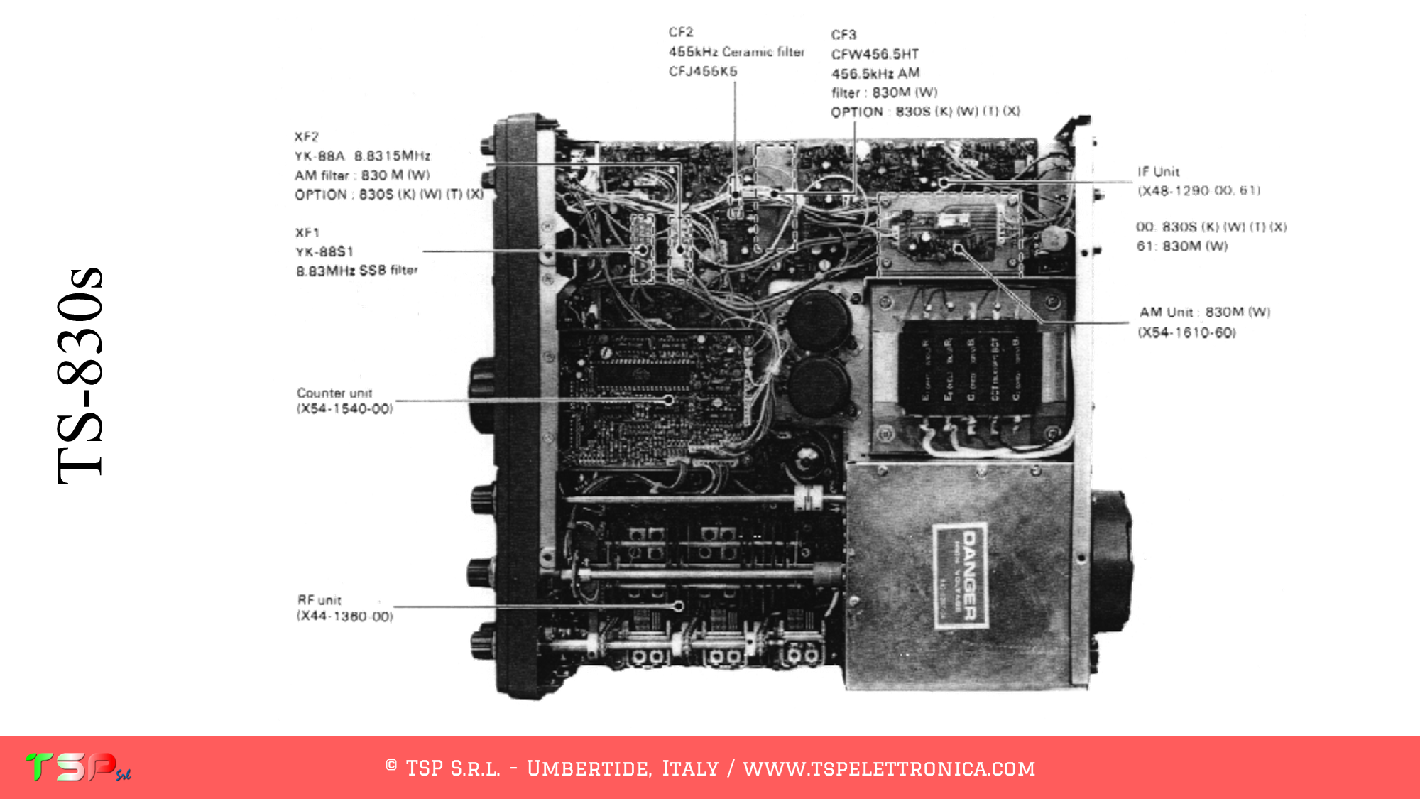
On the upperside of the radio, after removing the cover, locate the electronic board called “RF Unit”: this is shown in the following picture.

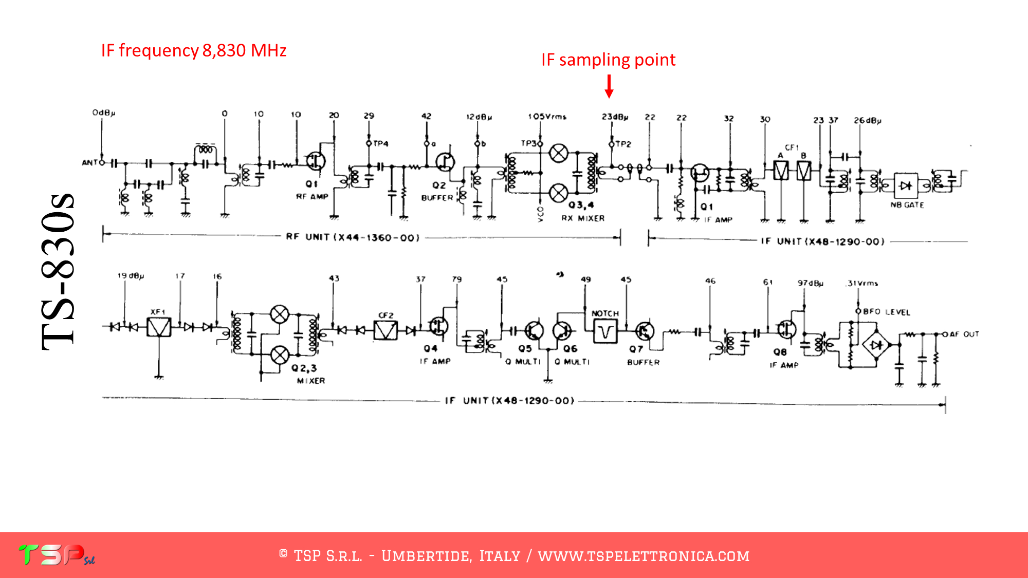
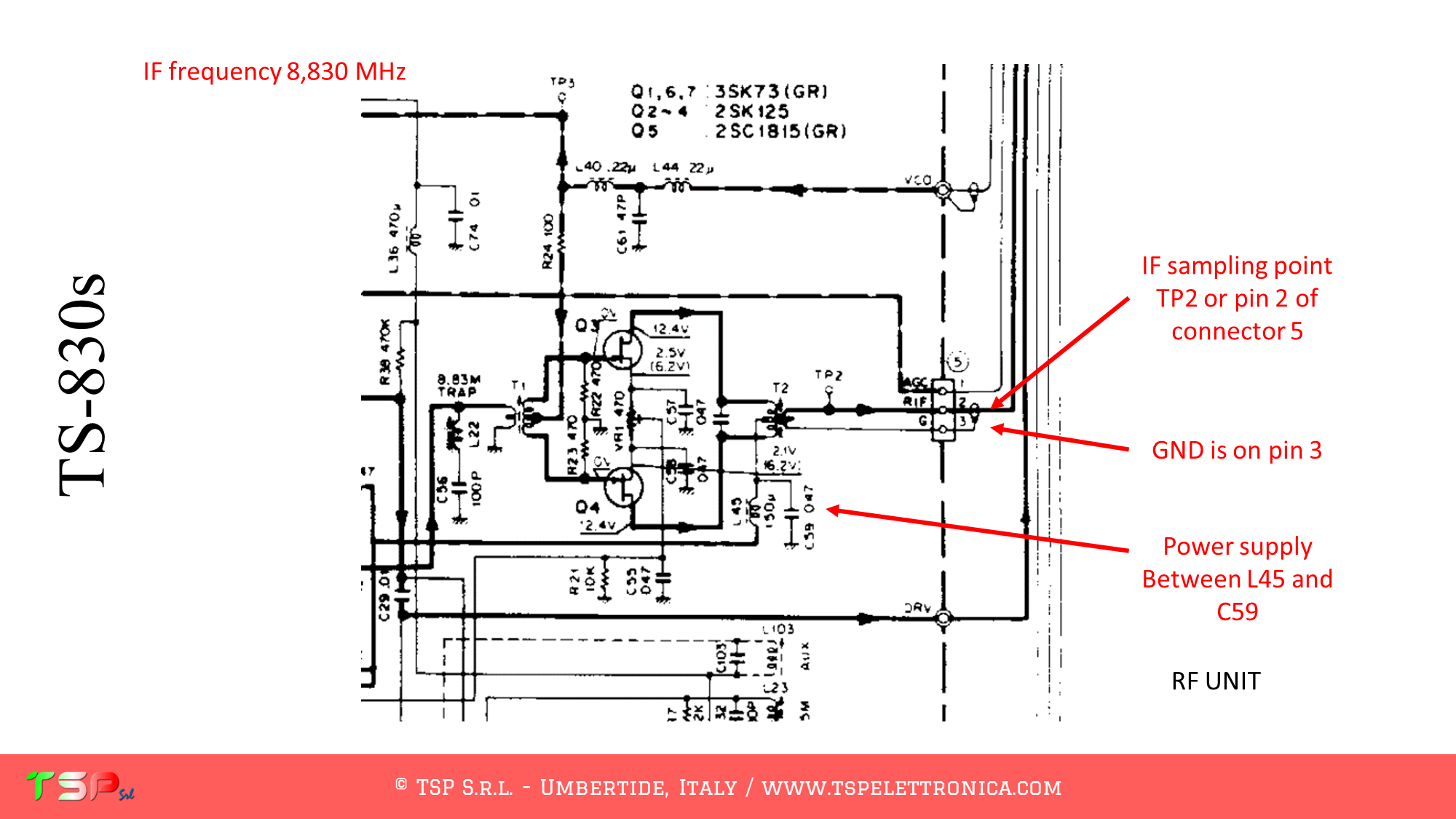
Refer to the following images of the wiring diagram to identify the points where you can weld the cables for the IF, power supply and PTT.

Refer to the following image to identify the points on the PCB where to weld the various connecting cables.

In order to buy an IFace please use the following buttons.

Paypal

ATTENTION: Though installing the IFace is not difficult, you do this at your own risk. TSP S.r.l. is not responsible for any damage, unwanted side-effects or whatever.

For more information do not hesitate to write us.
Have fun!
© TSP S.r.l. | VAT IT03137540542 | V.le Unità d'Italia 36, 06019 Umbertide, ITALY