In a previous
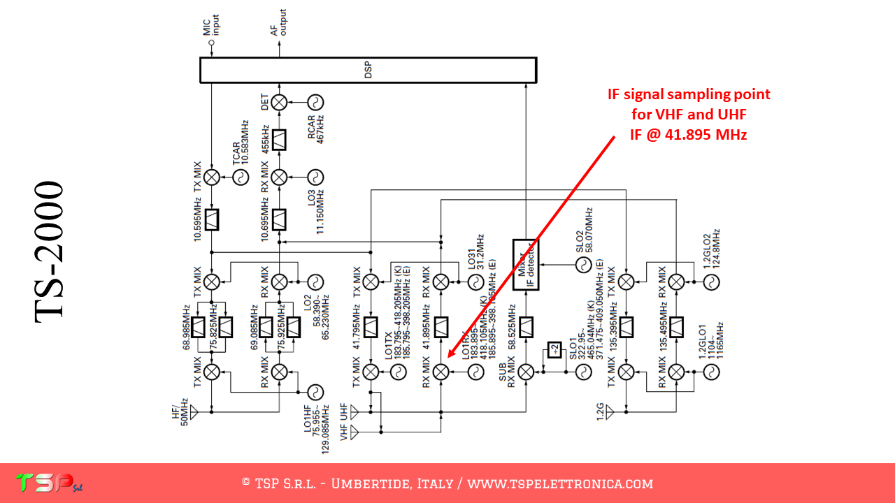
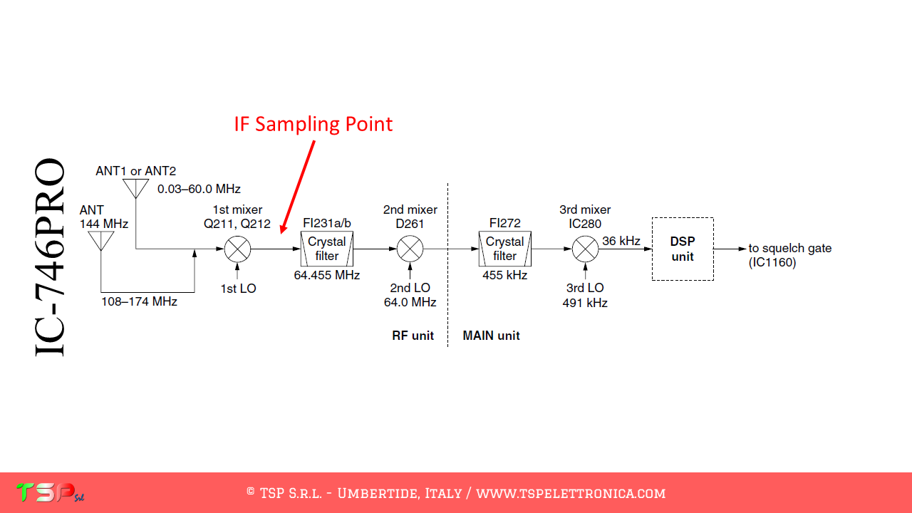
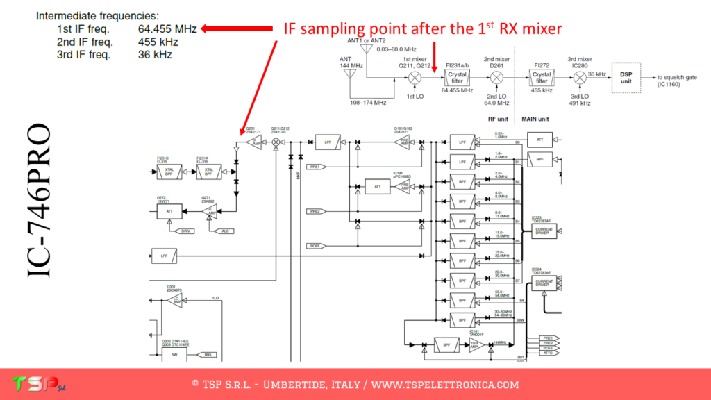
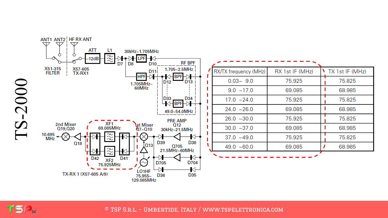
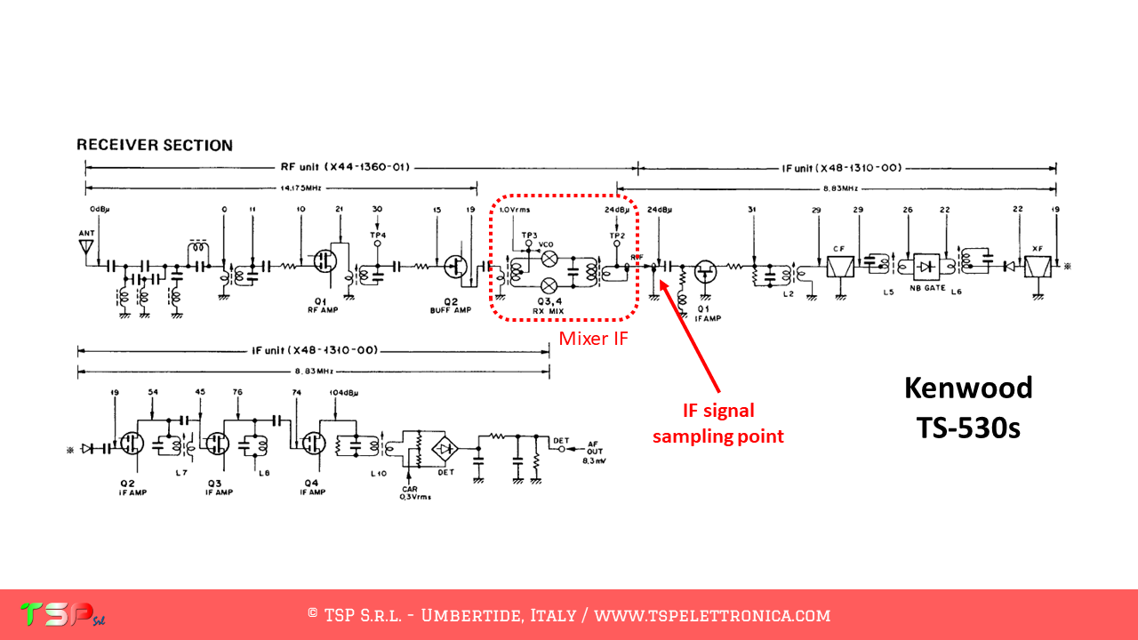
The TS-2000, like other radios, has a fairly complex configuration and uses different intermediate frequencies depending on the band on which you are operating. In any case, the one described here is the sequence of operations to be performed to obtain a bandwidth sufficient to provide a panoramic receiver around the IF frequency relative to the 23 cm band (1.2 GHz).
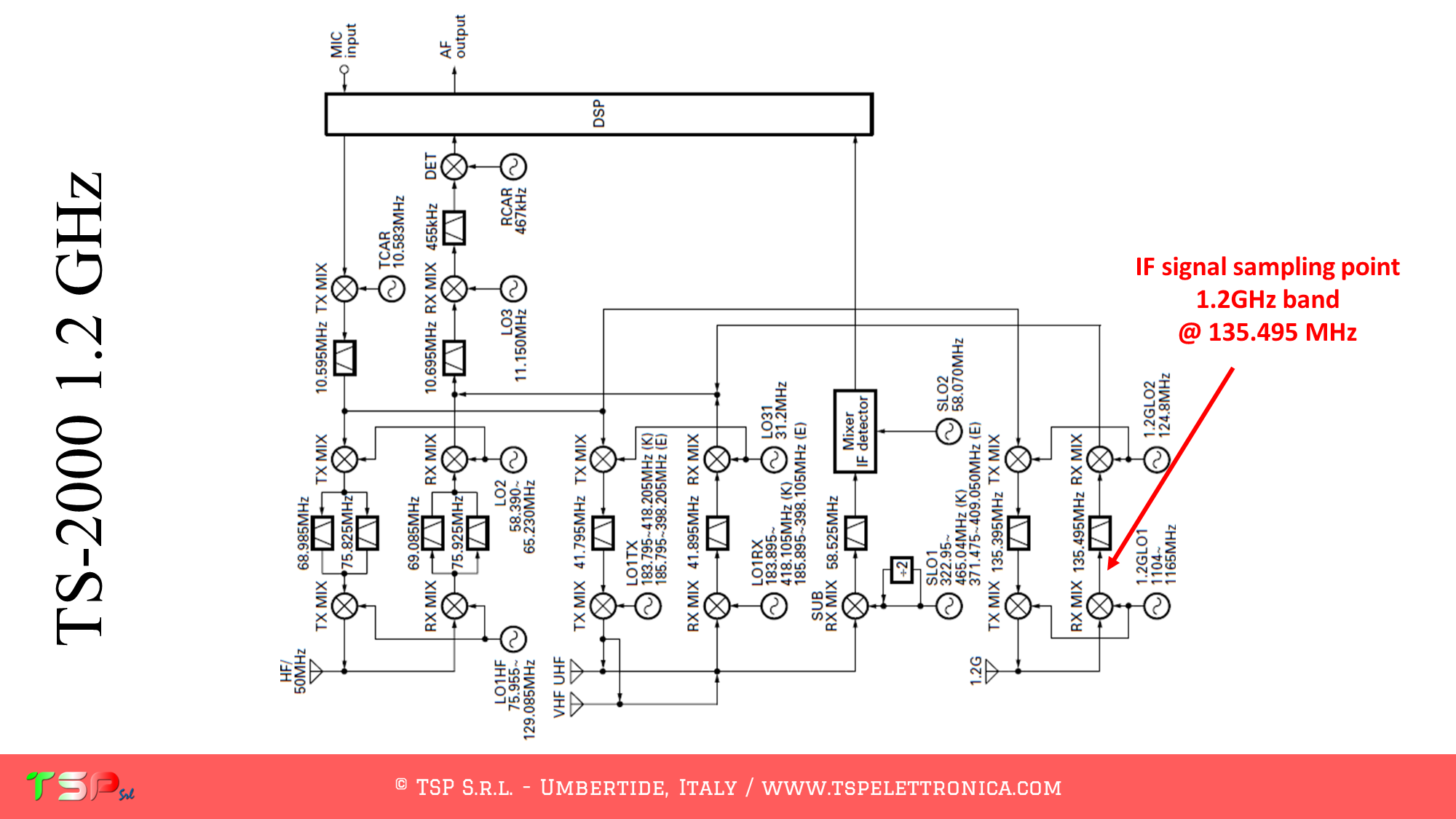
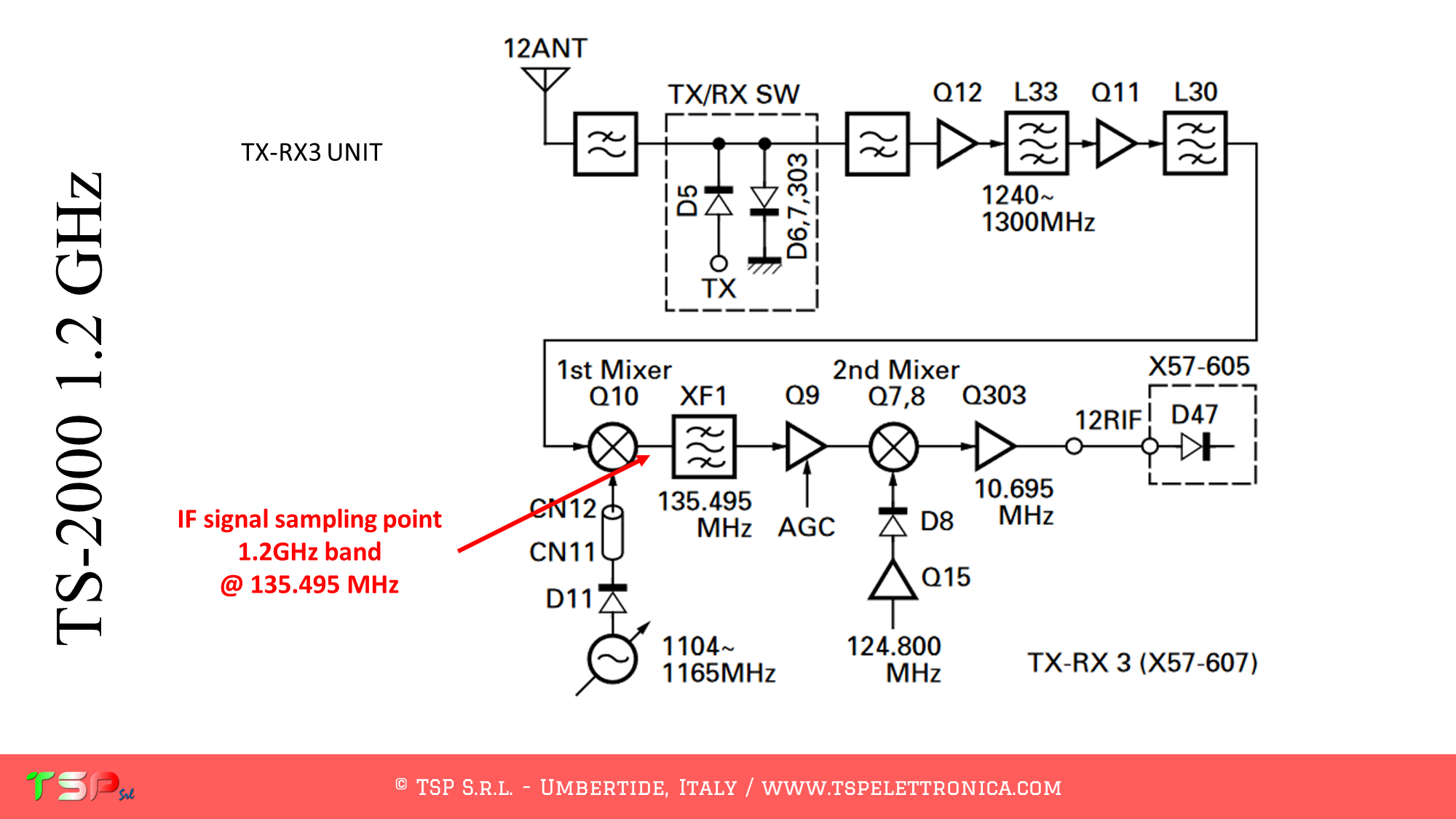
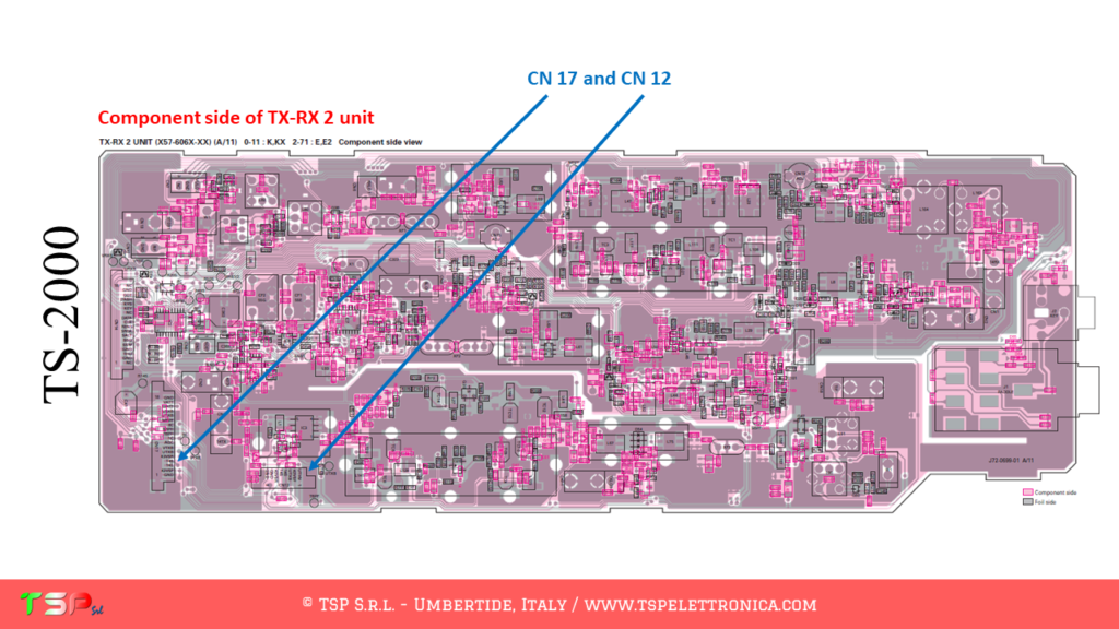
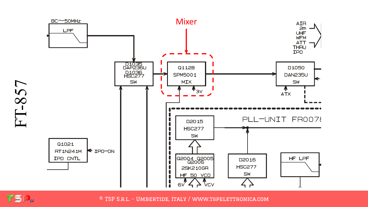
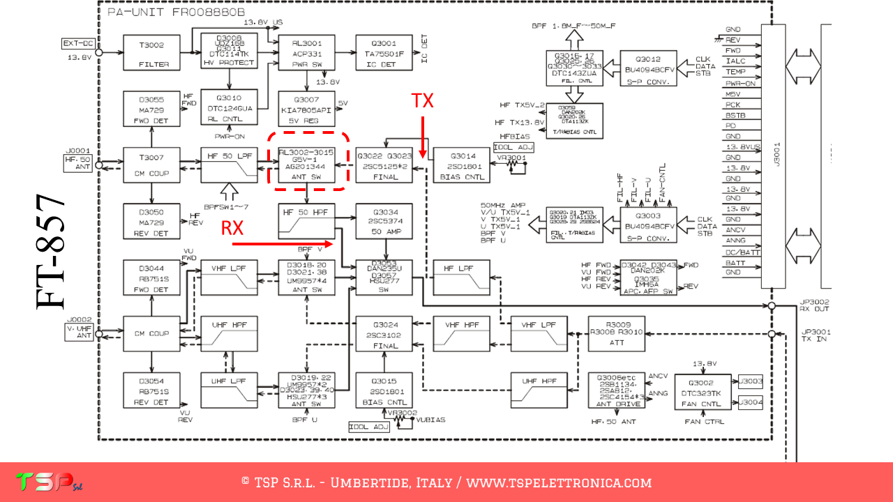
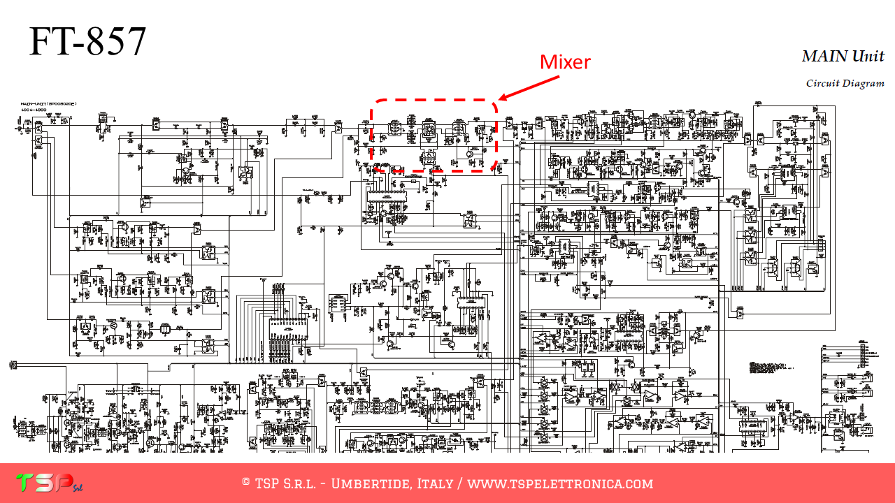
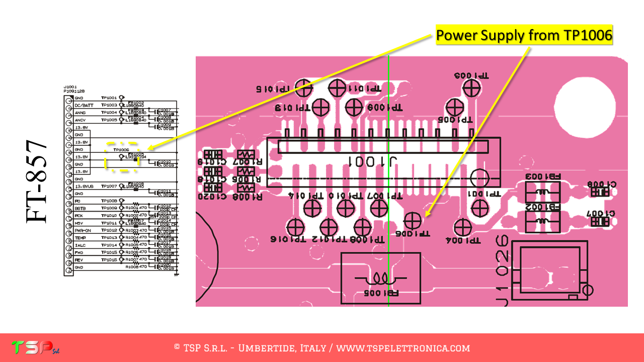
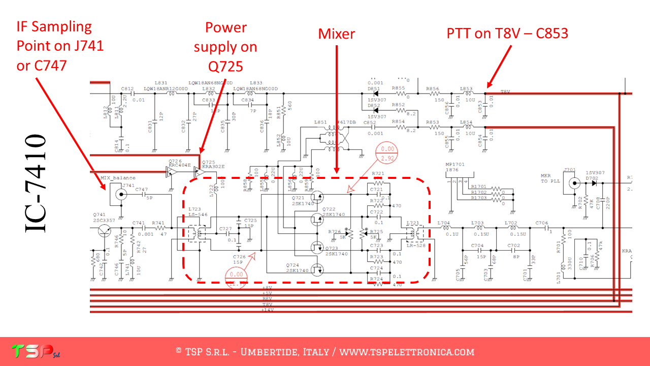
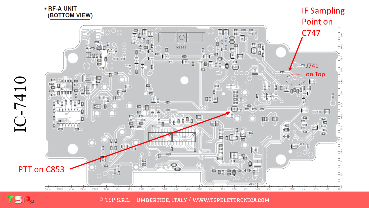
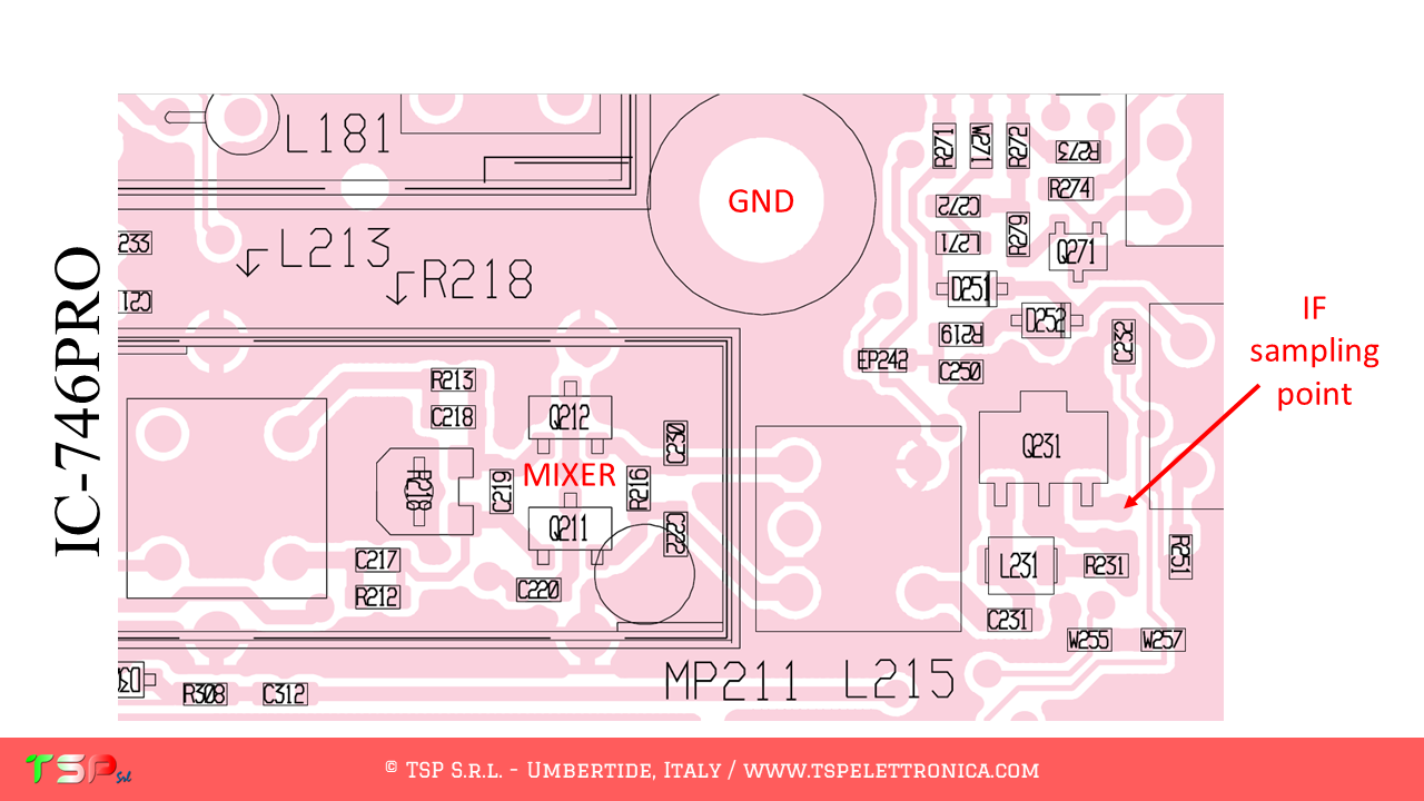
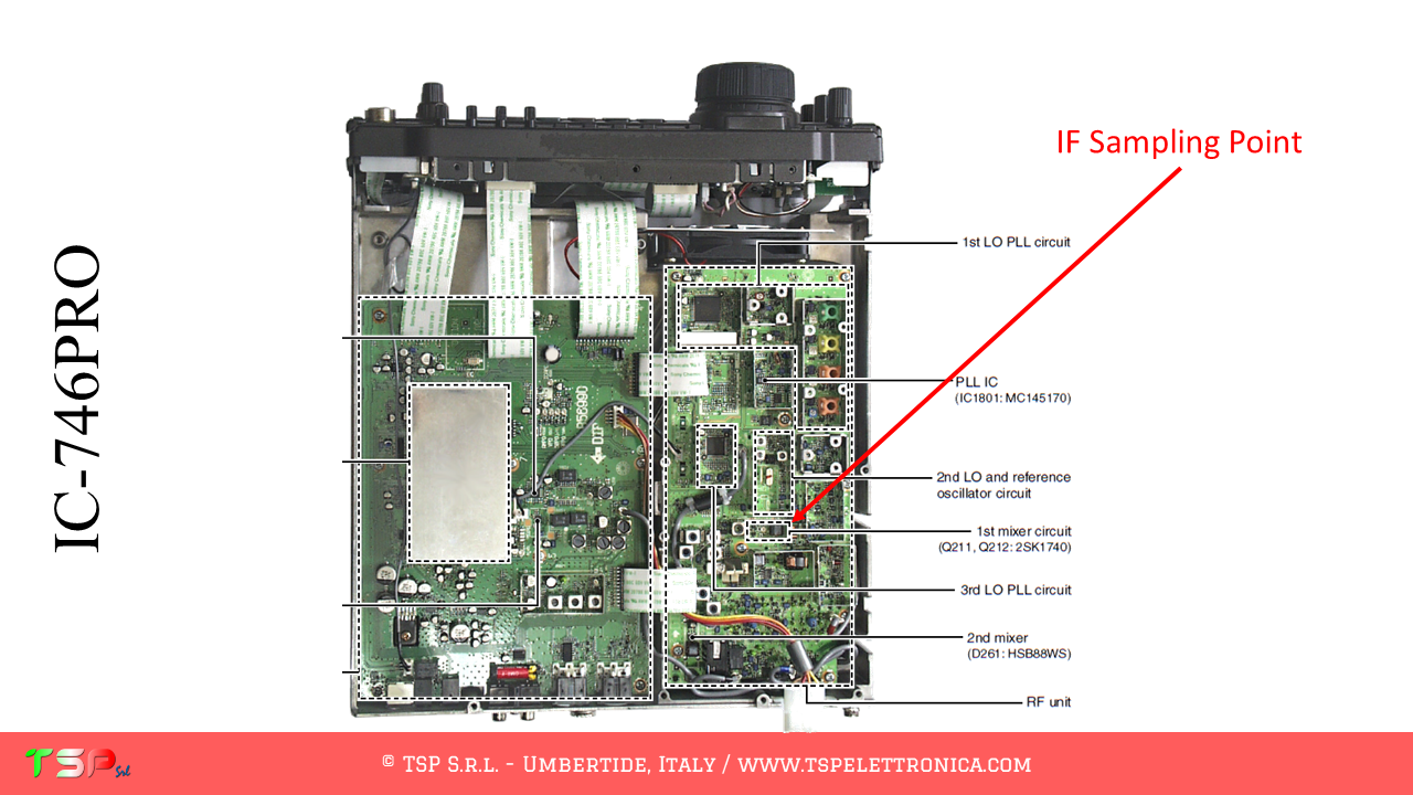
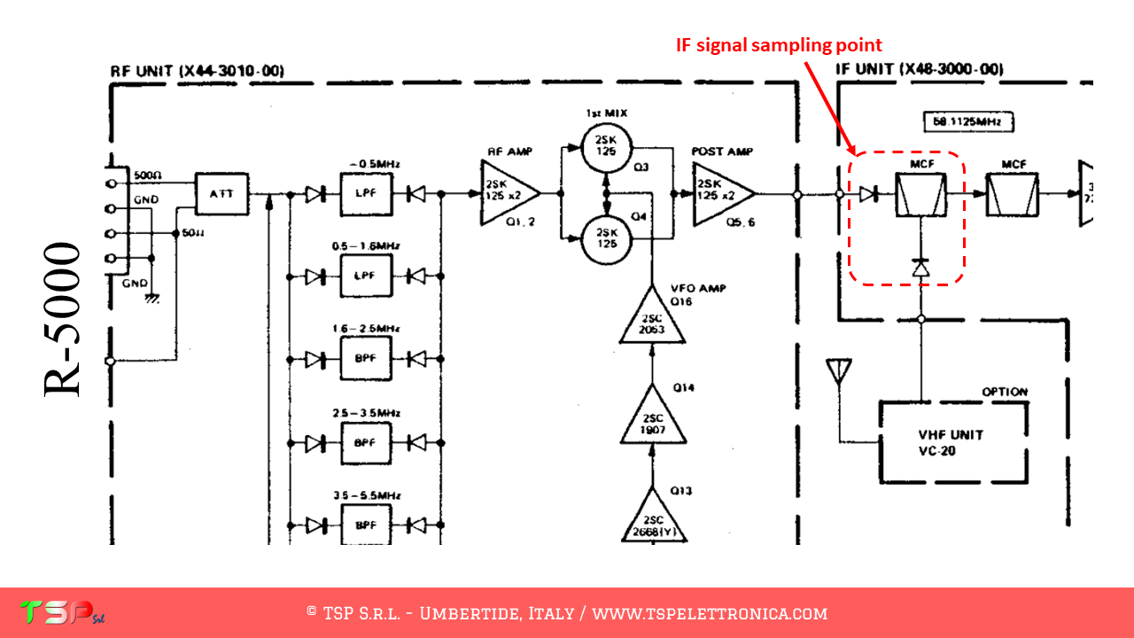
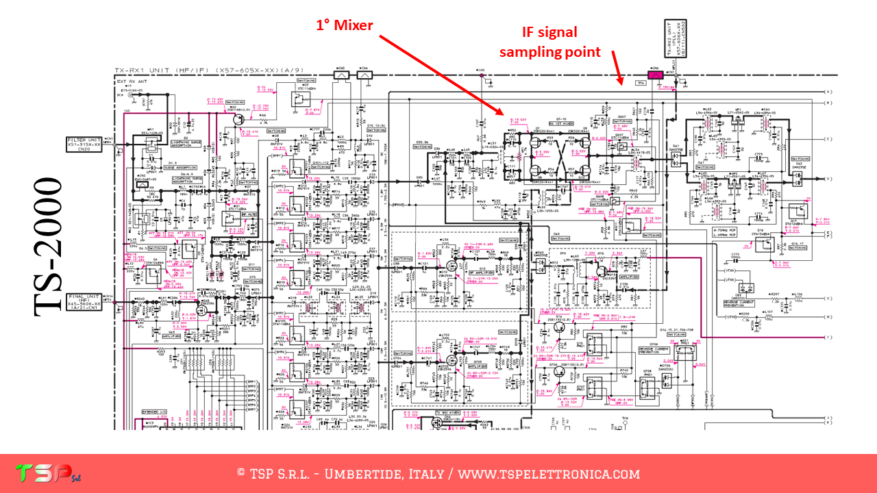
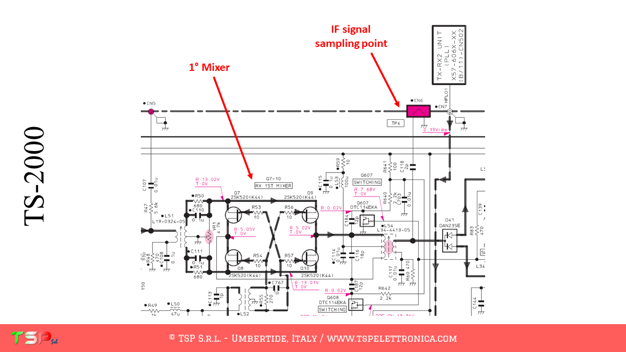
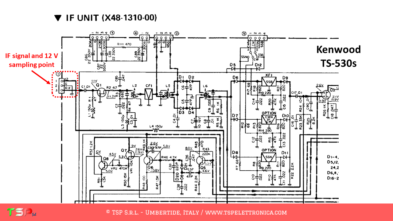
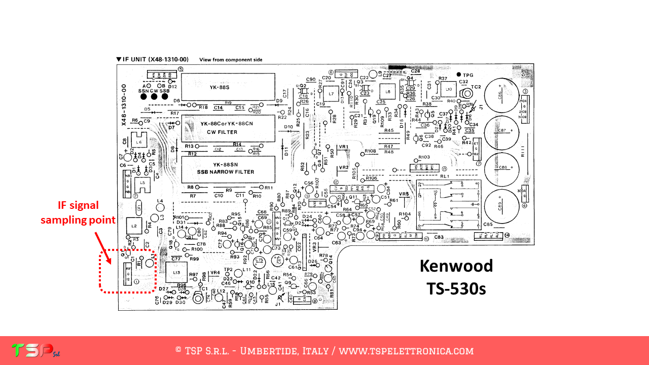
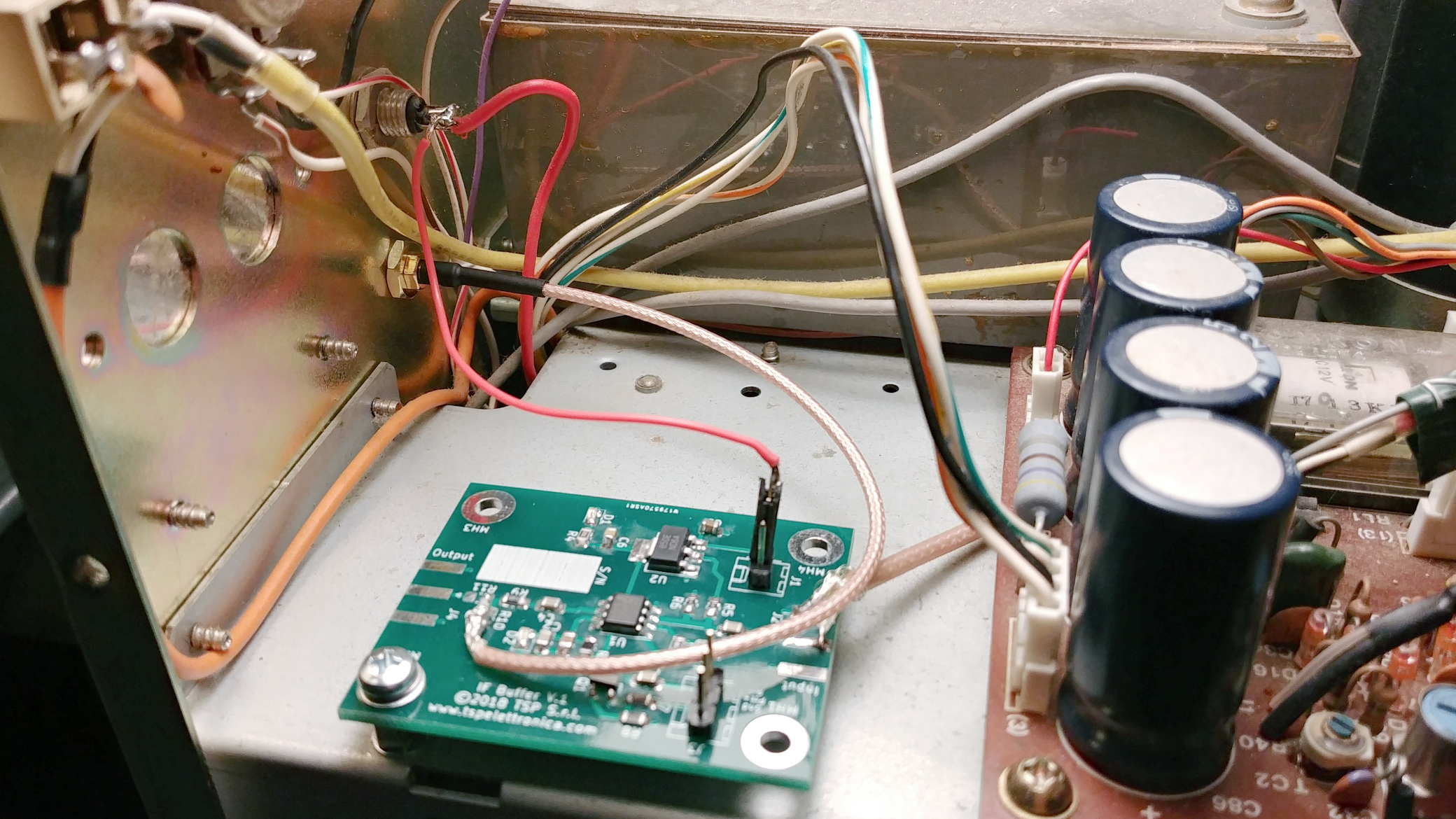
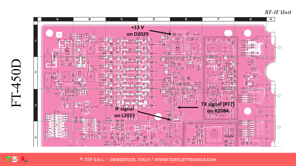
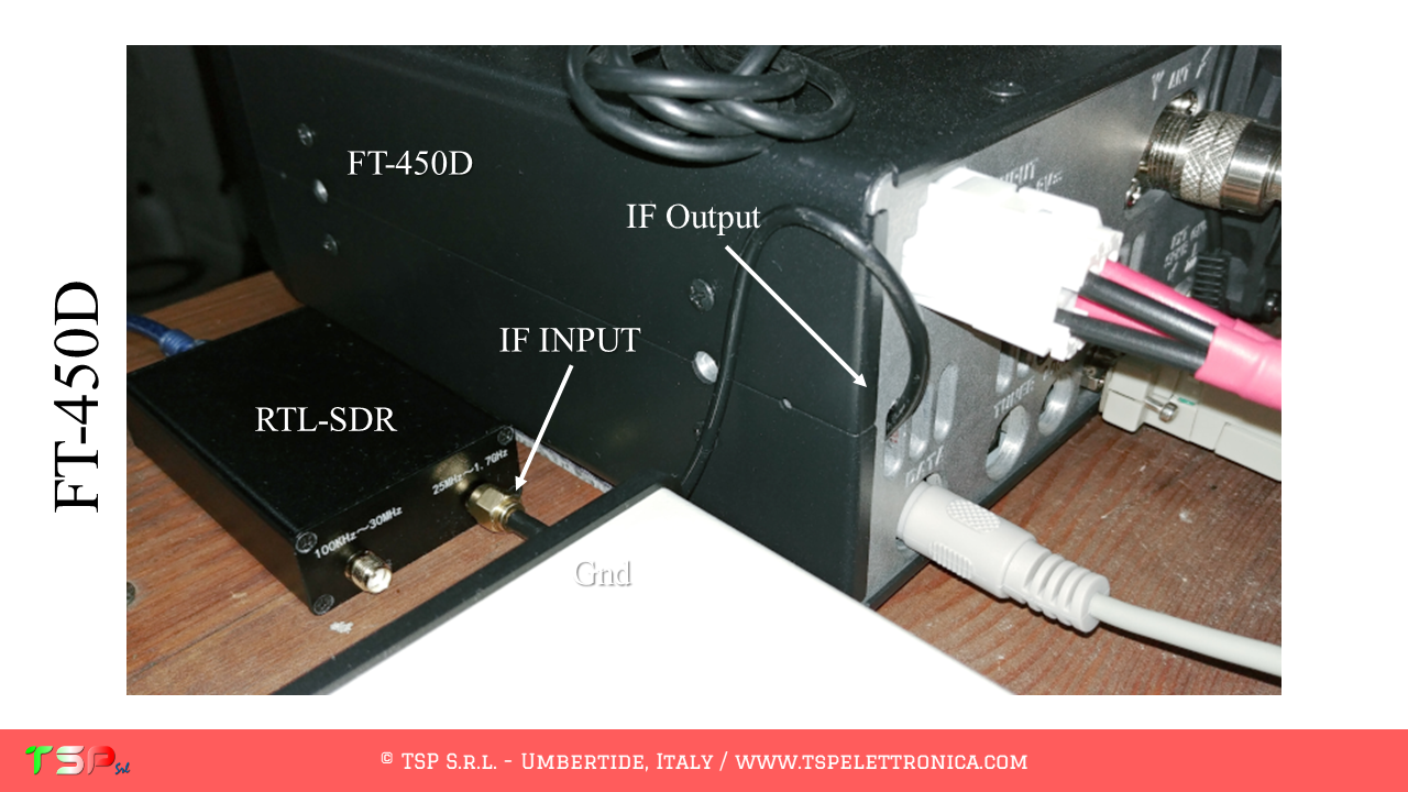
The point where to take the IF signal can be identified more precisely through the wiring diagram as shown in the following images. The electronic board of interest is the one called TX-RX3 and the signal can be taken from the CN8 connector.

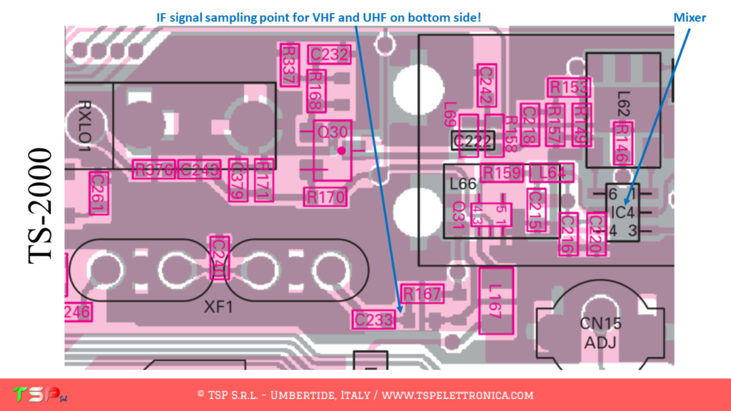
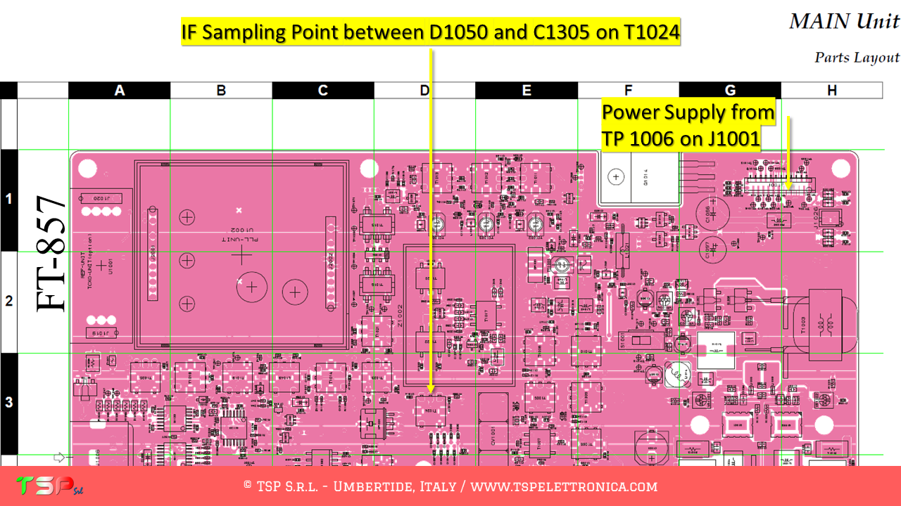
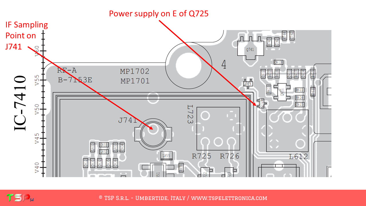
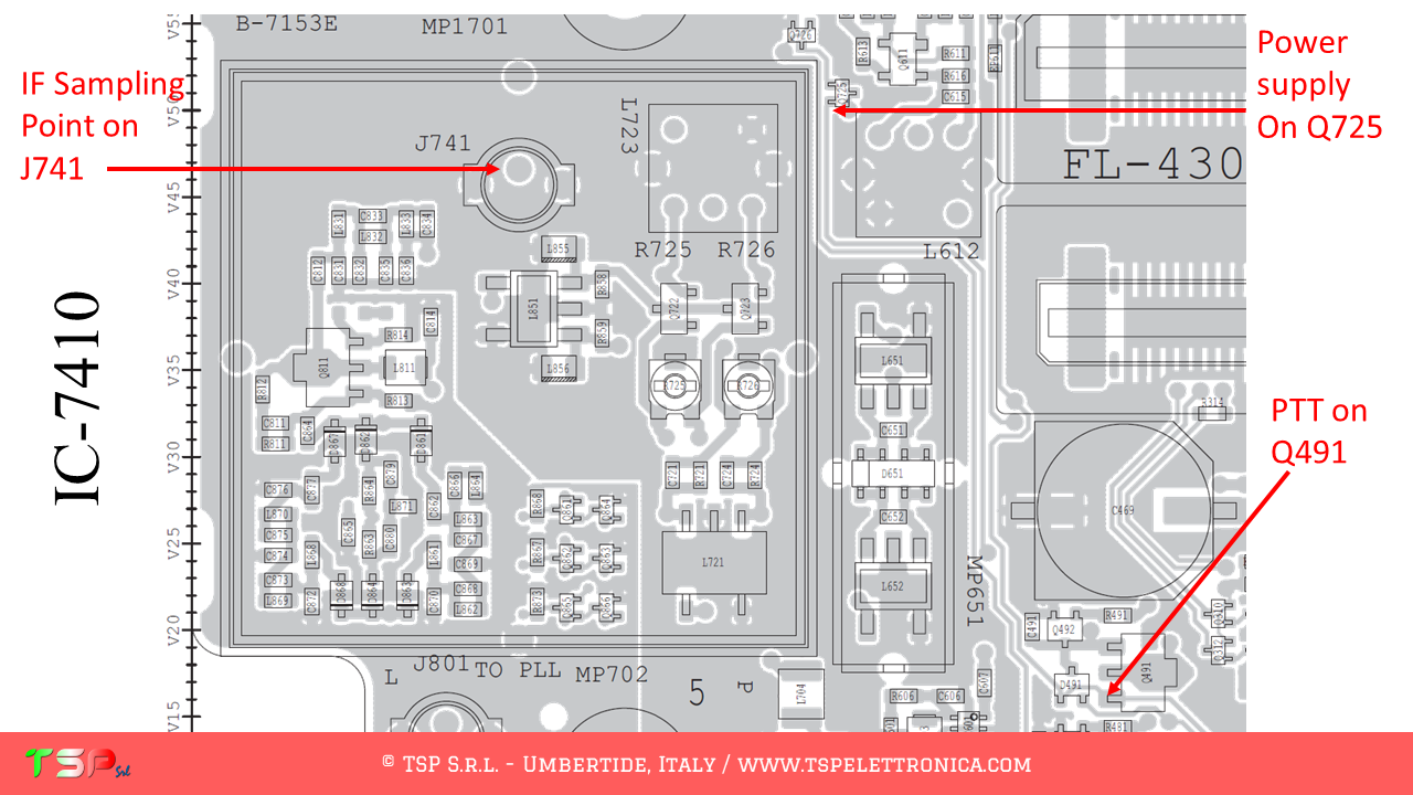
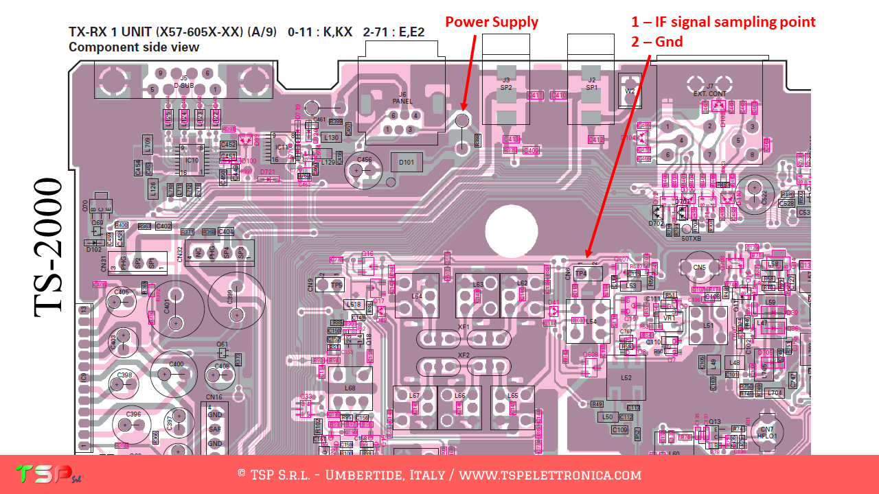
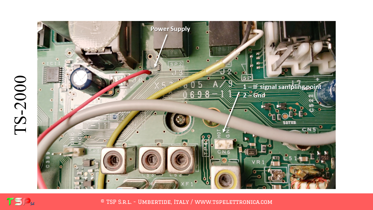
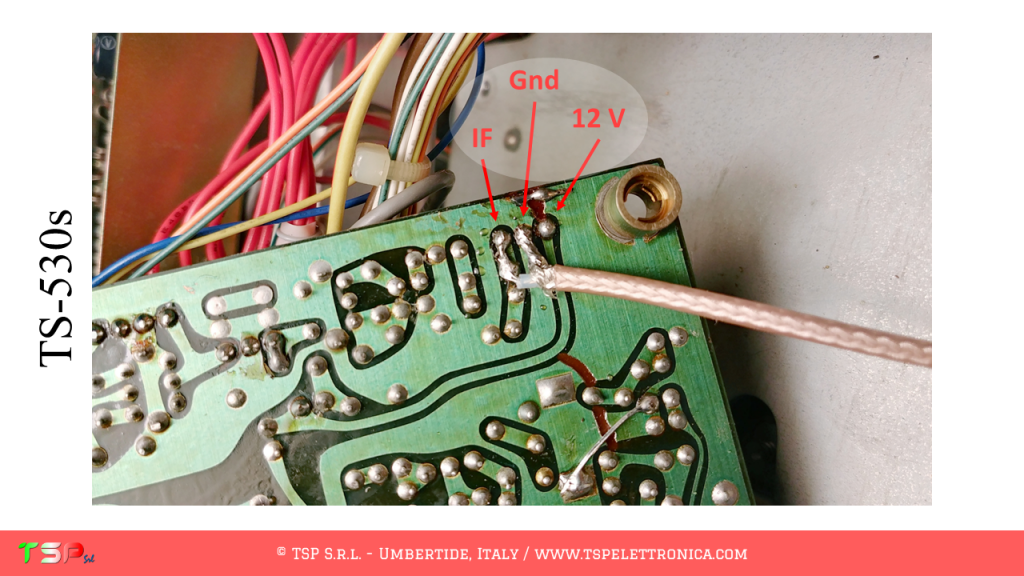
The point where to take the IF signal on the TX-RX3 UNIT is indicated in the following image.

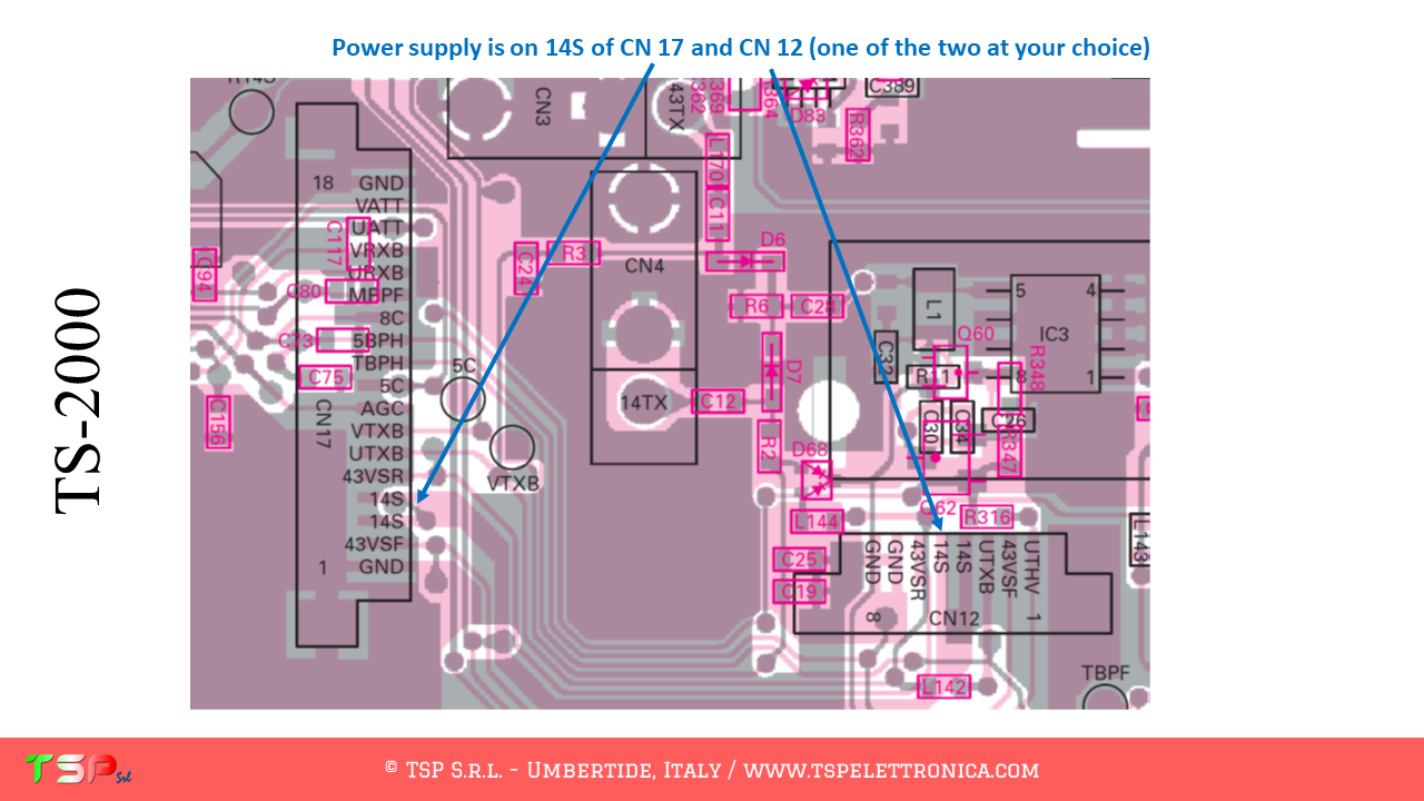
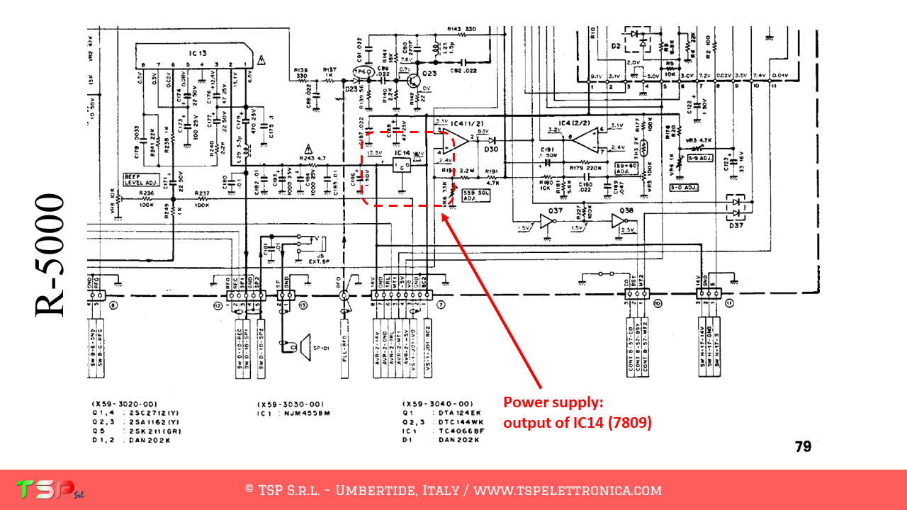
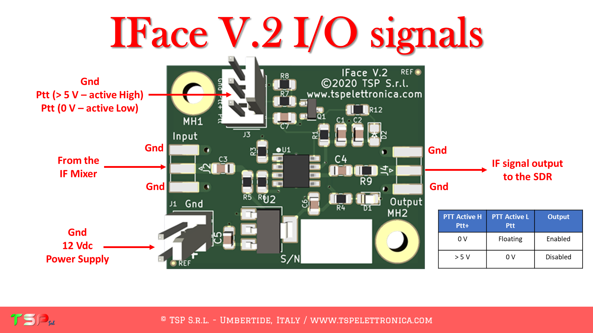
For the sake of completeness, a detail of the point where to take the power supply for the IFace card is also indicated.

PTT: This is not required for the TS-2000 as the reception circuit is muted during transmission.
You can purchase IFace 2 using one of the buttons below.

ATTENTION: Though installing the IFace is not difficult, you do this at your own risk. TSP S.r.l. is not responsible for any damage, unwanted side-effects or whatever.
For more information do not hesitate to write us.
Have fun!