SDR interface for the TS-570D and the TS-570DG

These are the instructions to install the IFace interface inside of the Kenwood TS-570D/G. The installation is very easy.

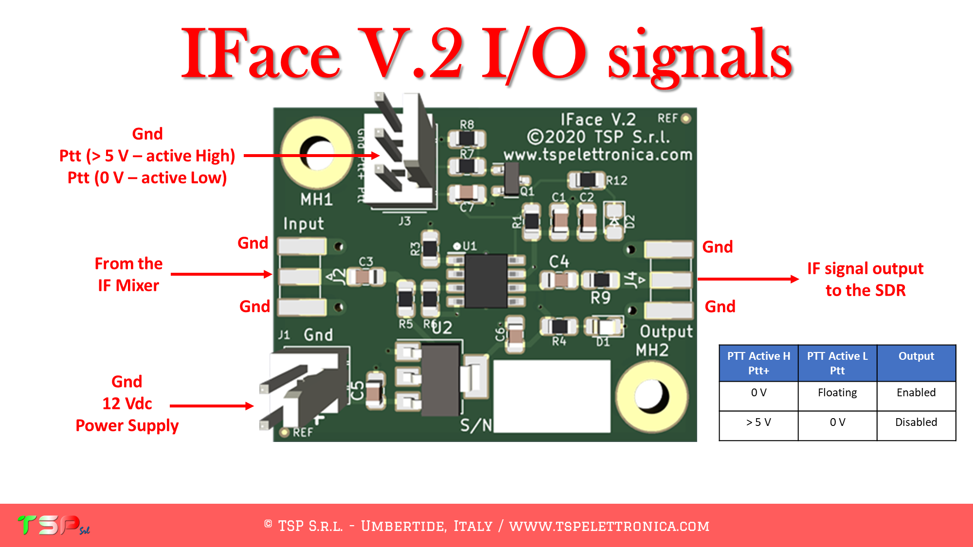
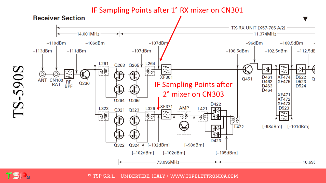
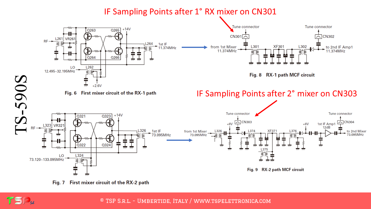
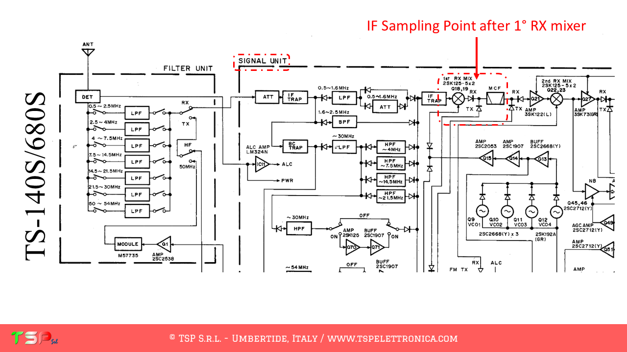
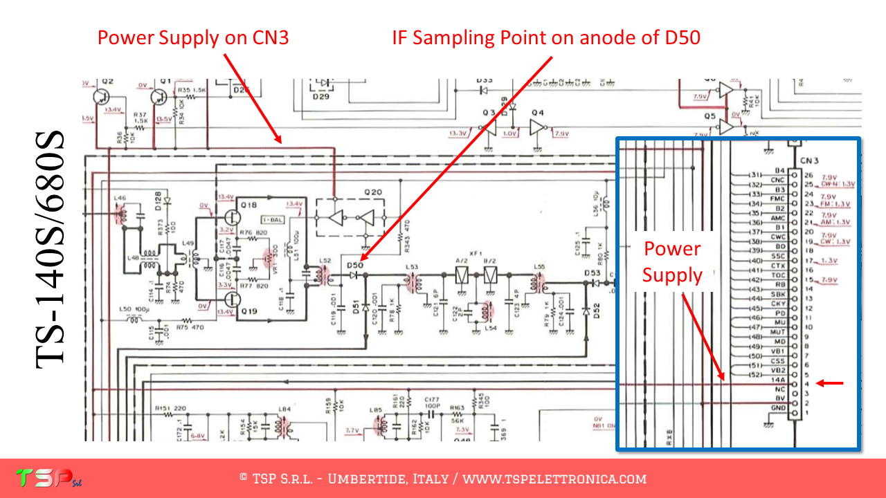
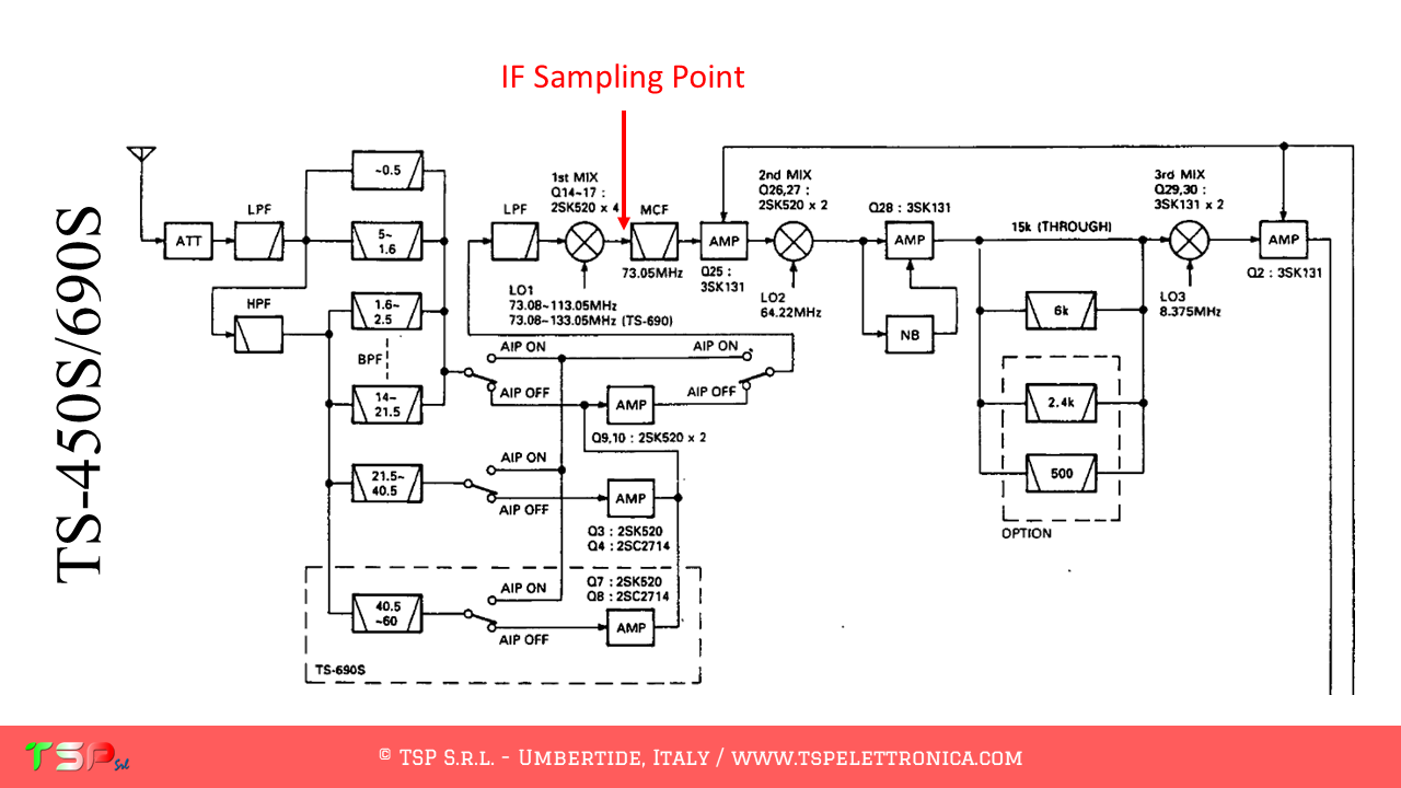
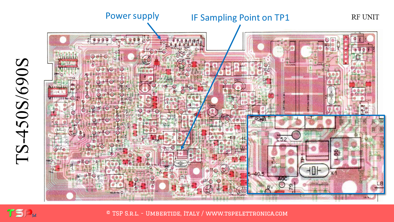
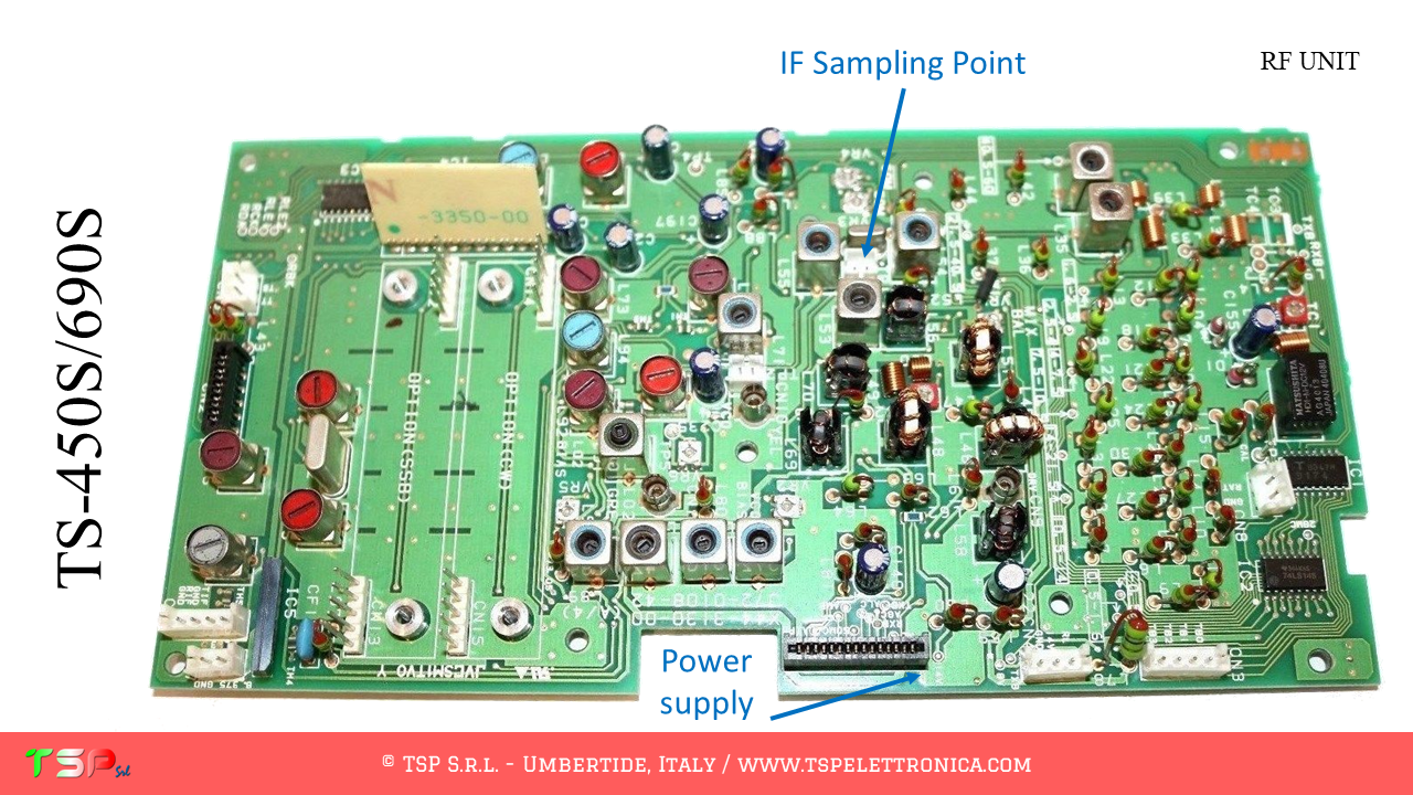
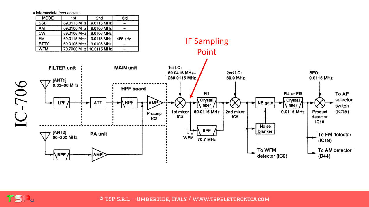
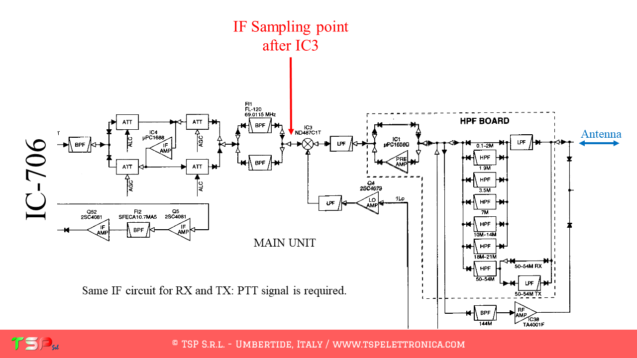
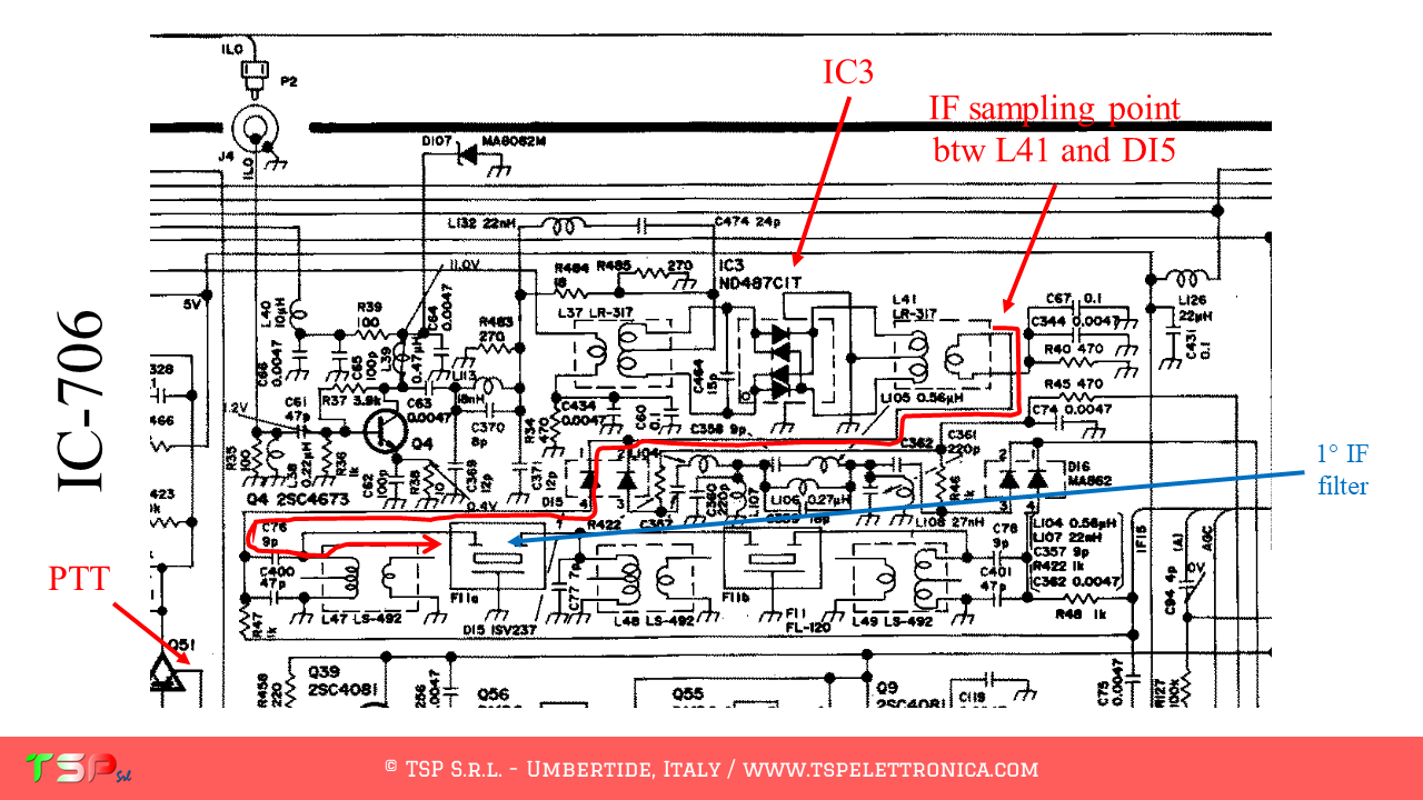
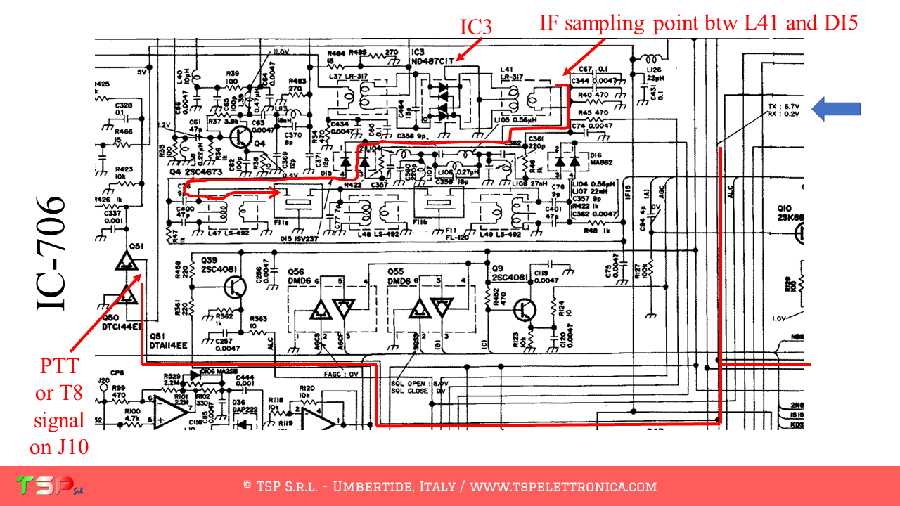
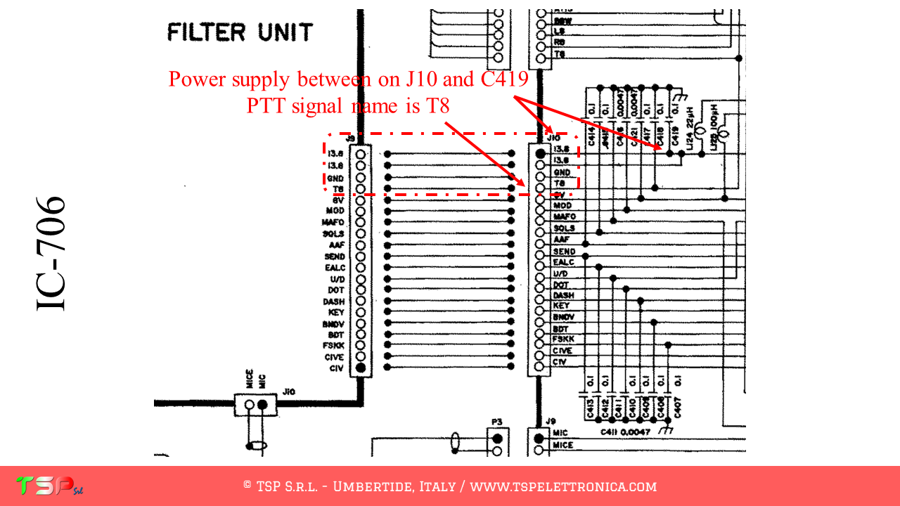
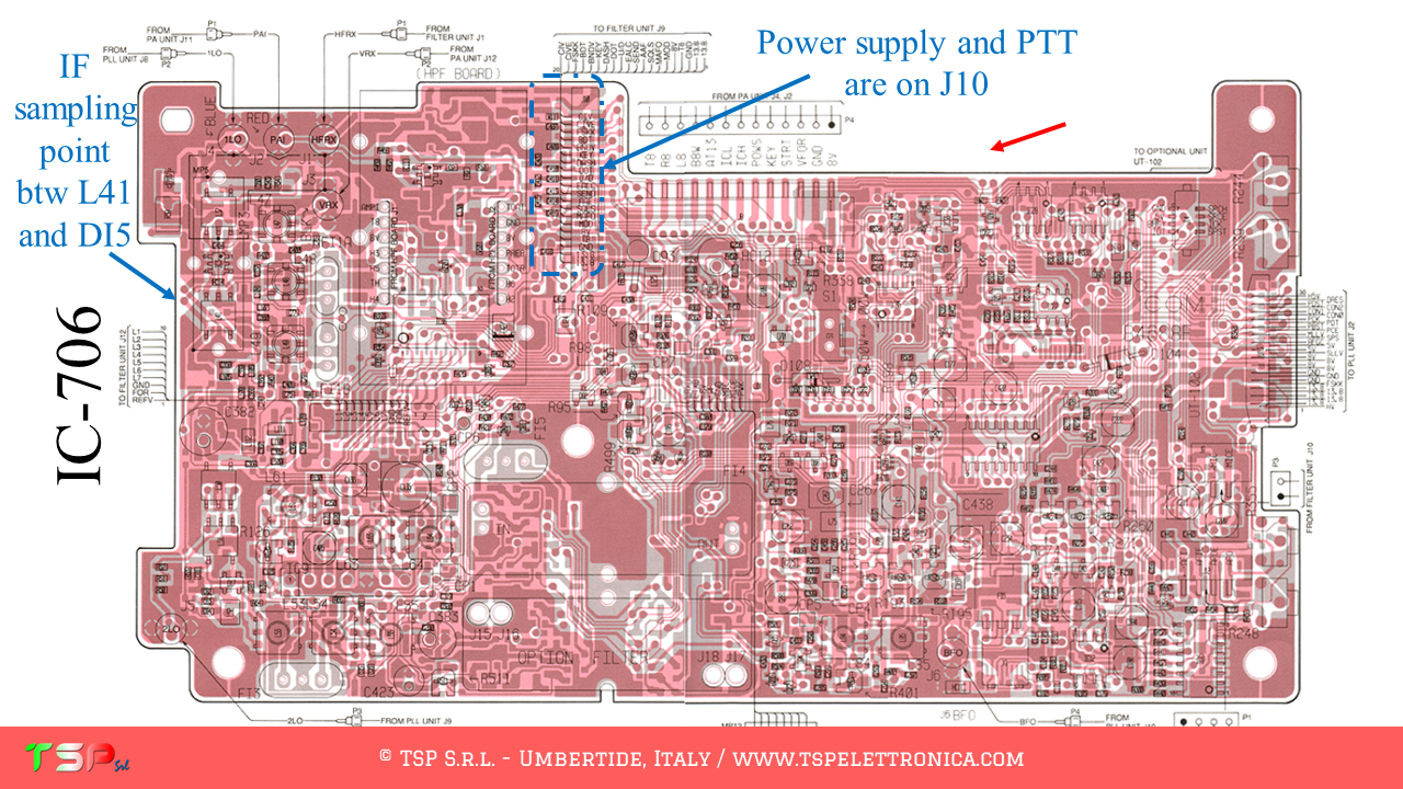
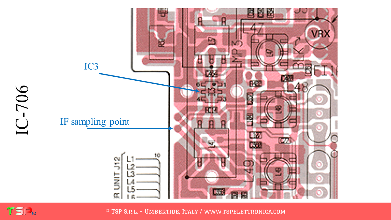
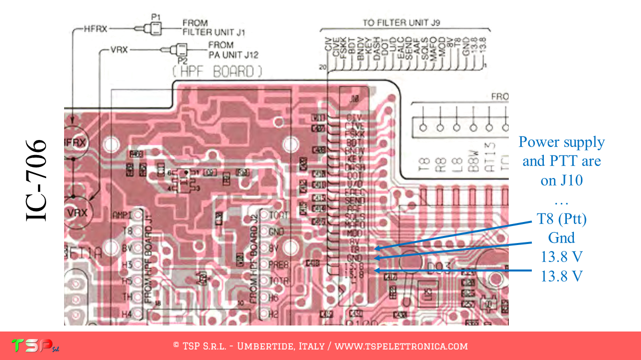
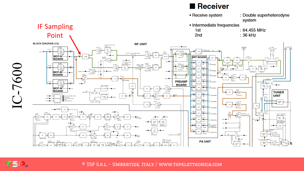
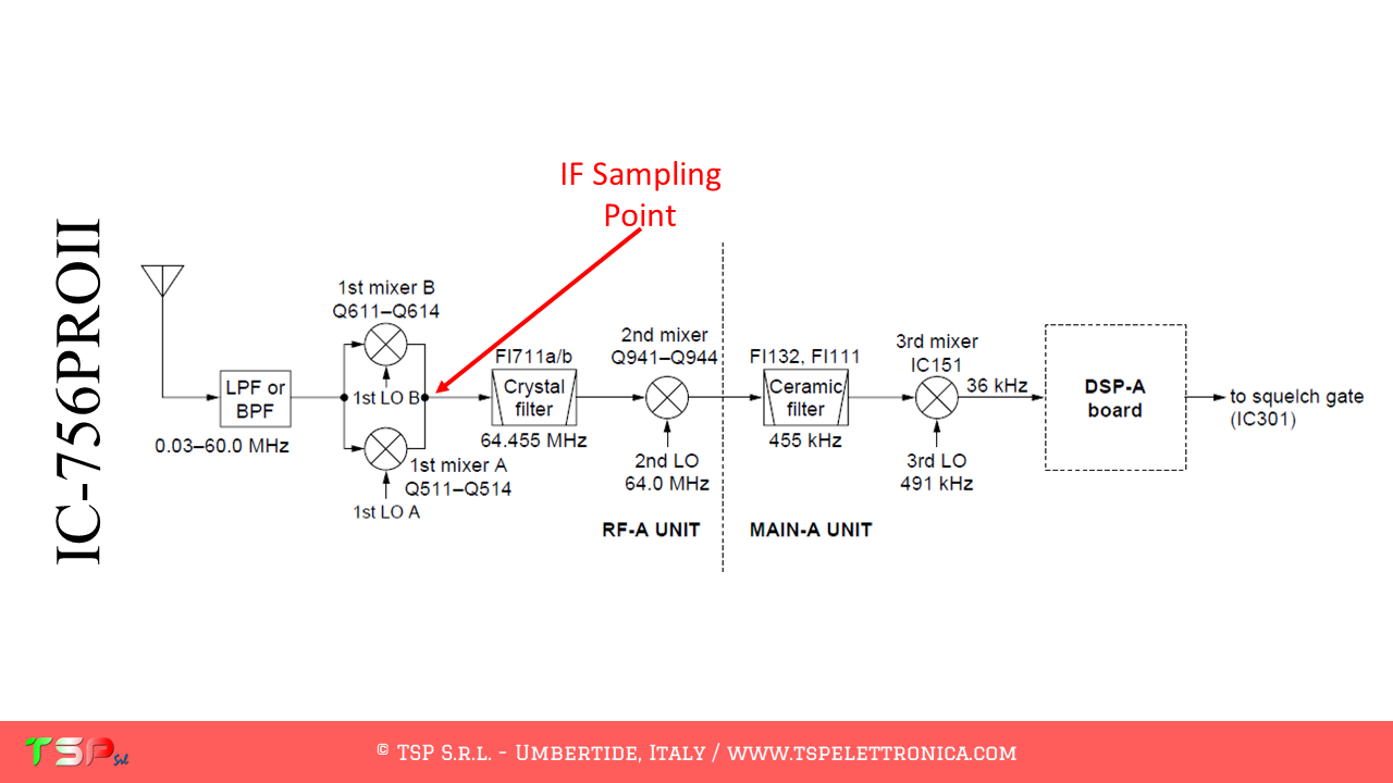
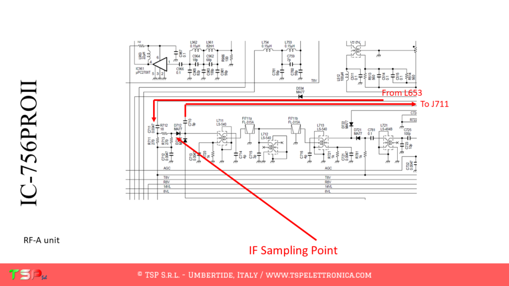
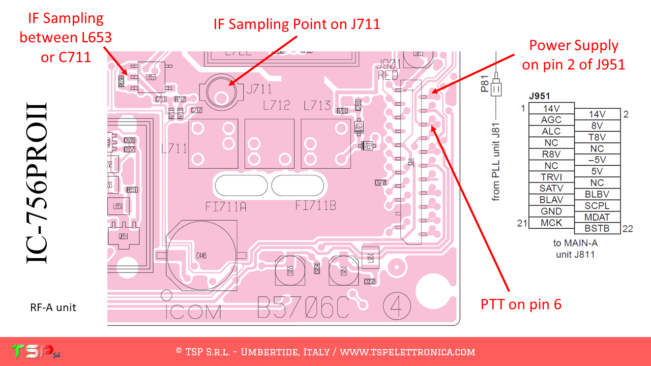
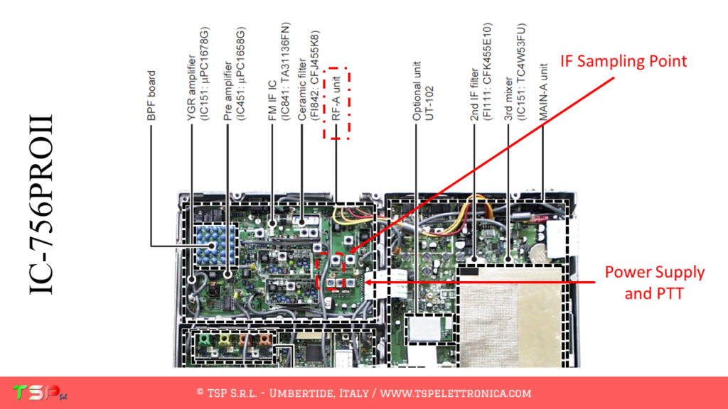
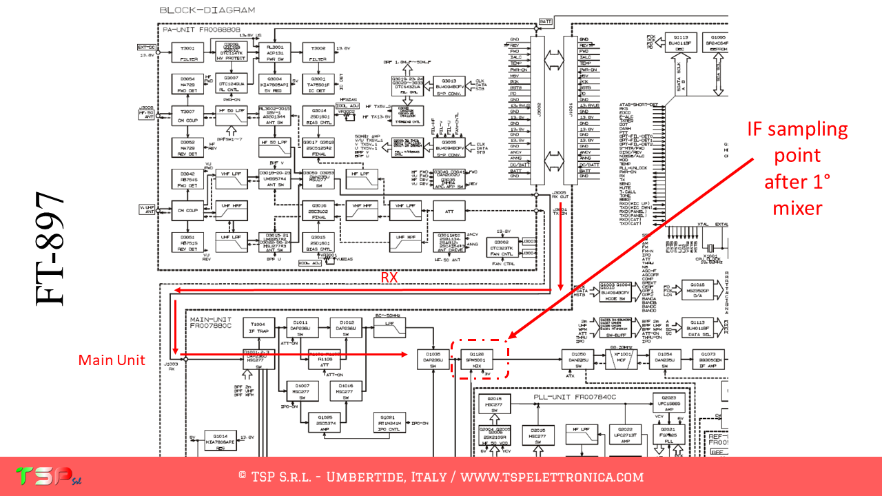
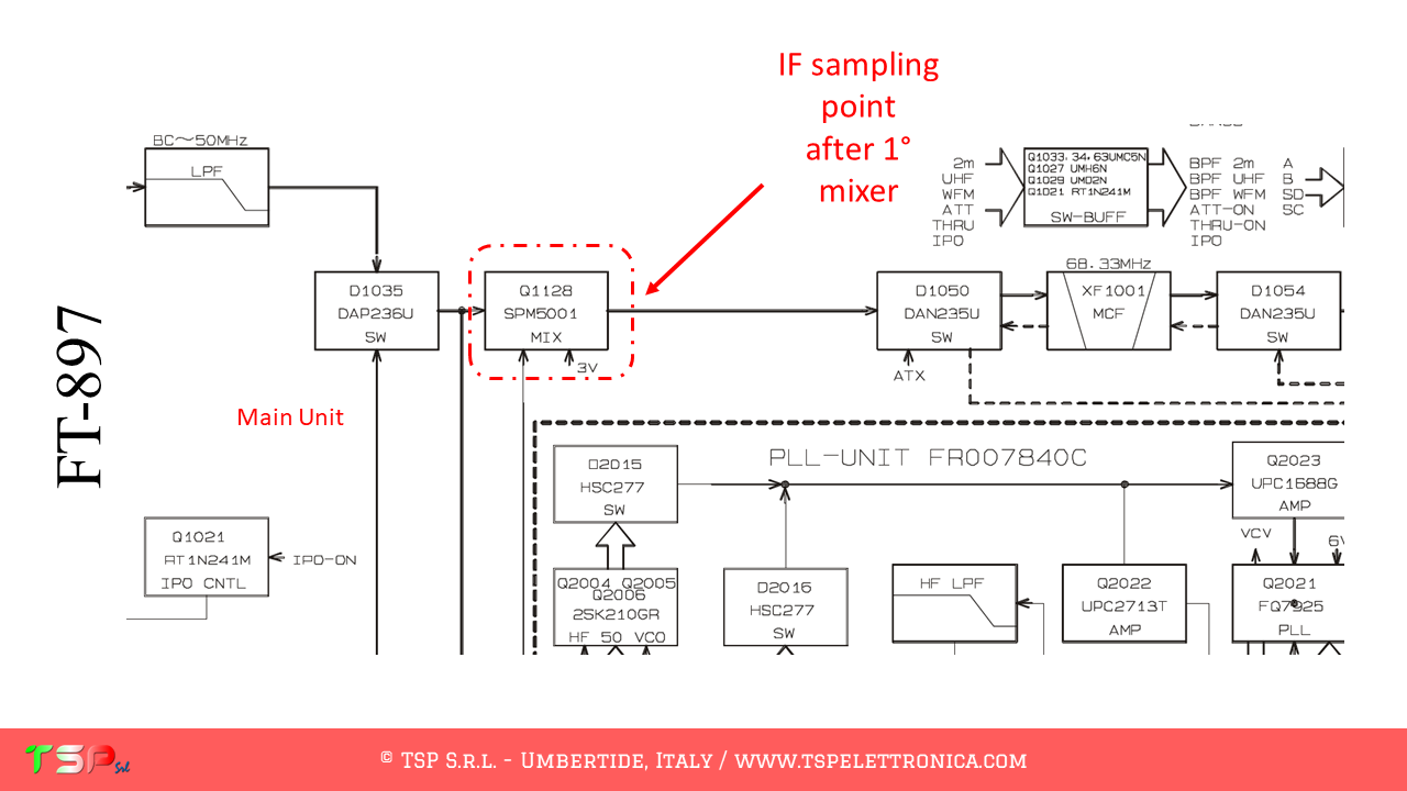
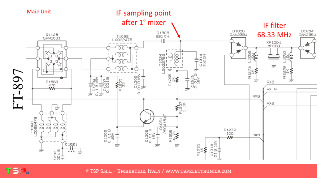
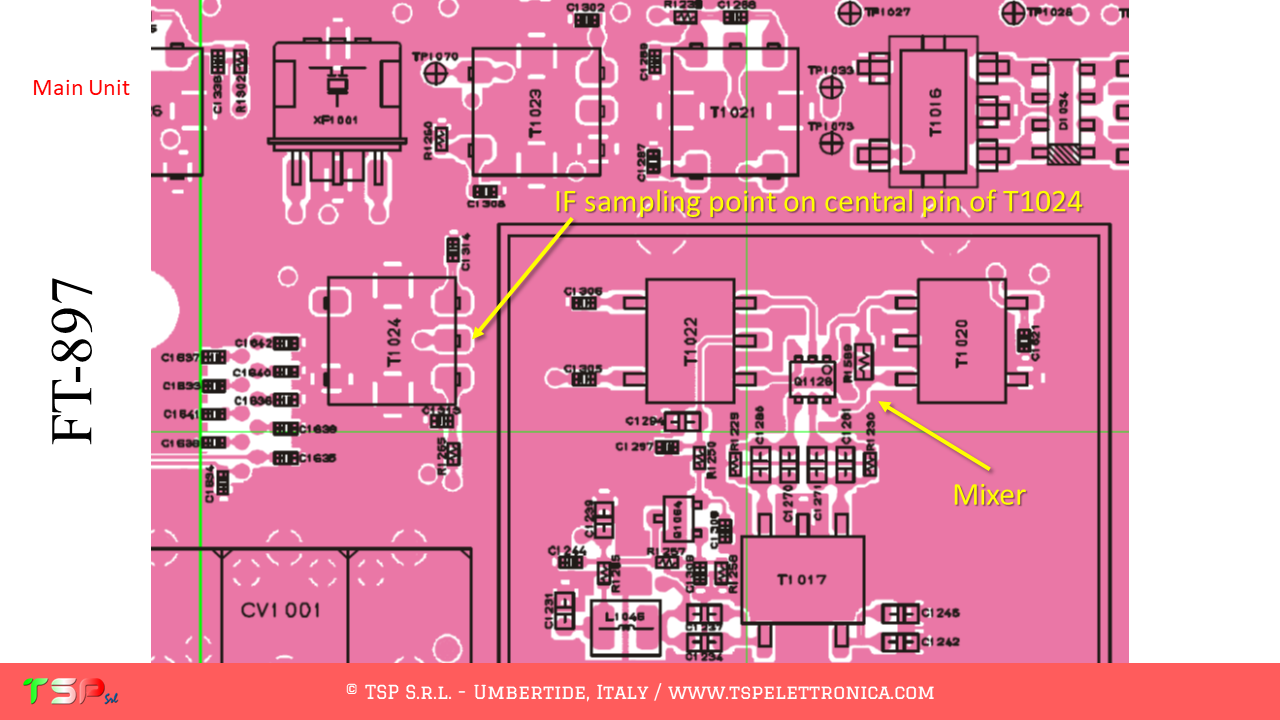
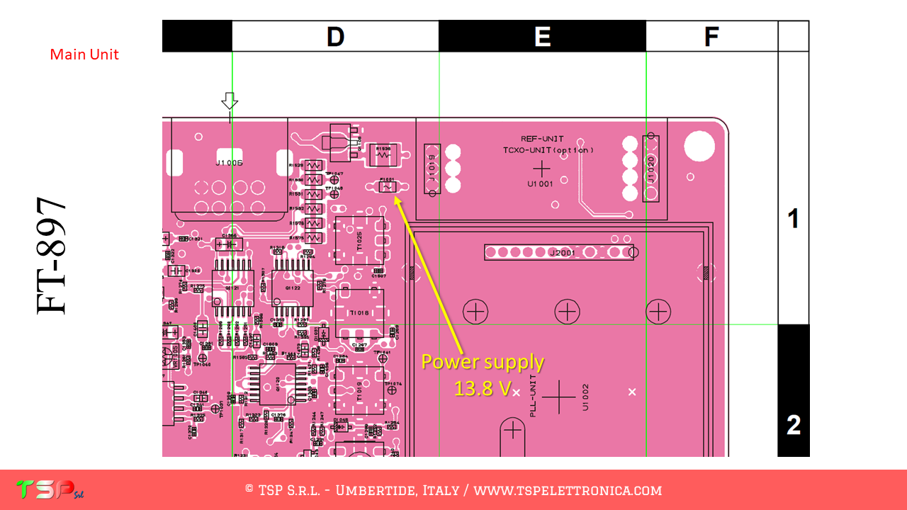
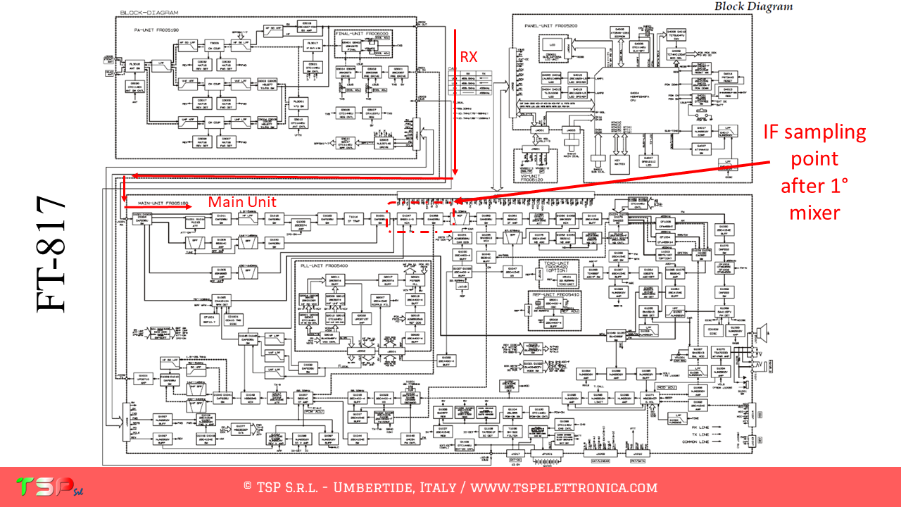
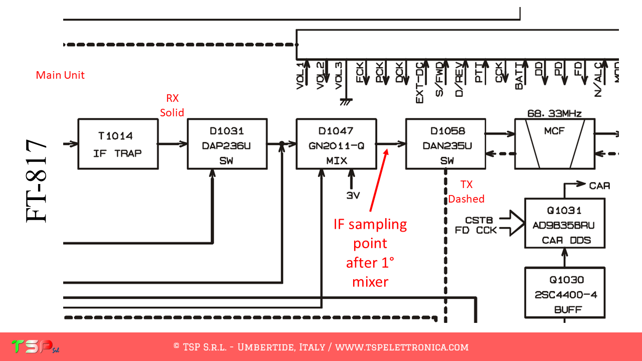
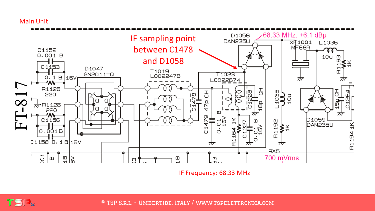
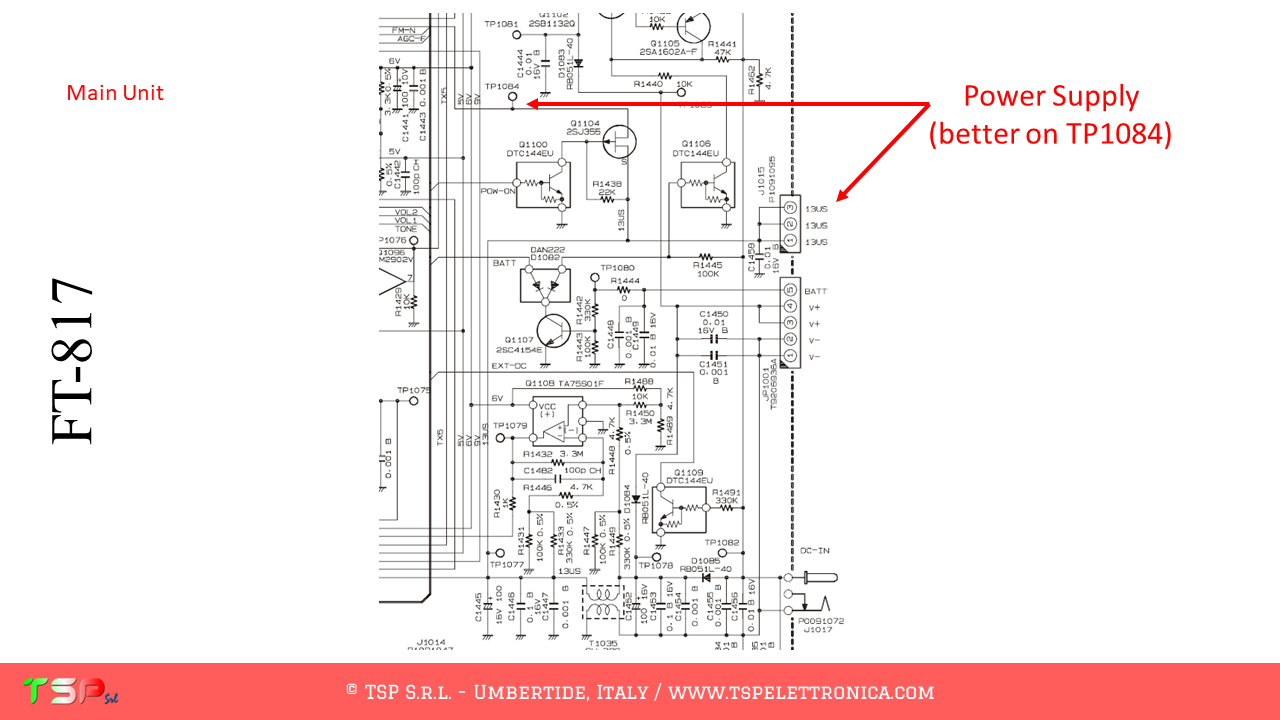
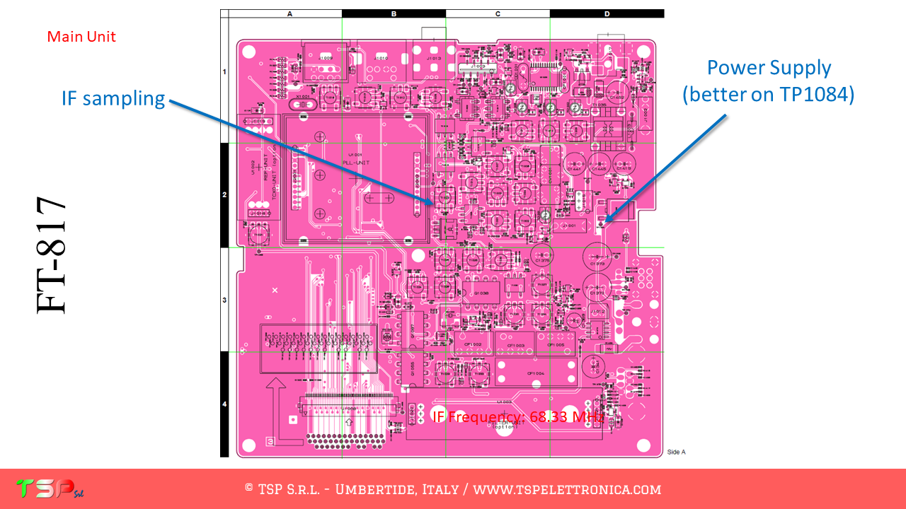
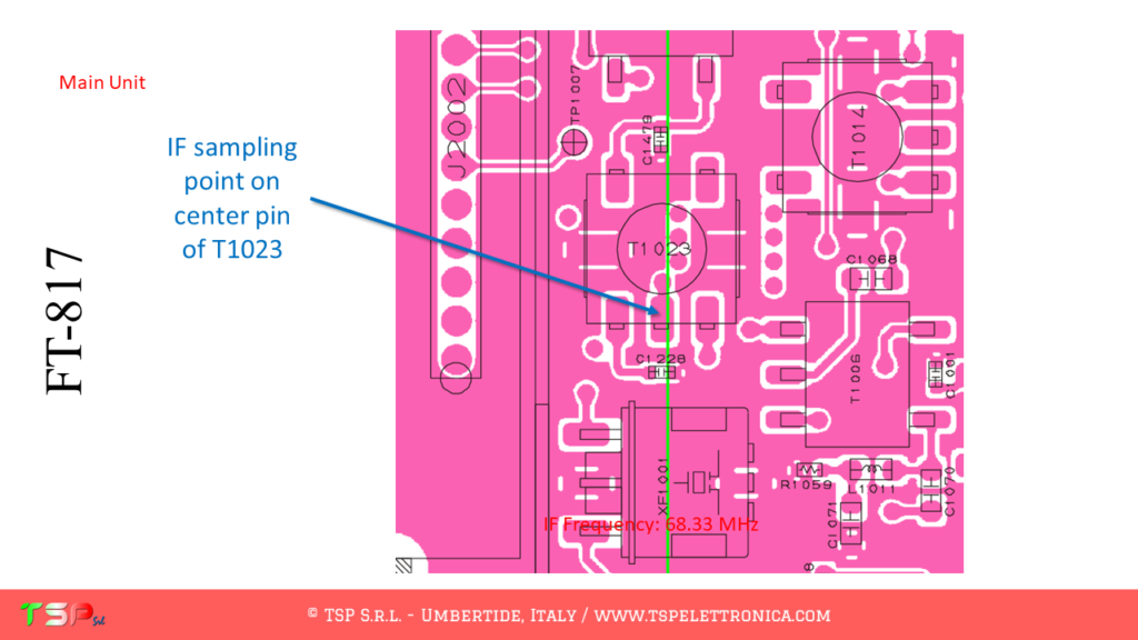
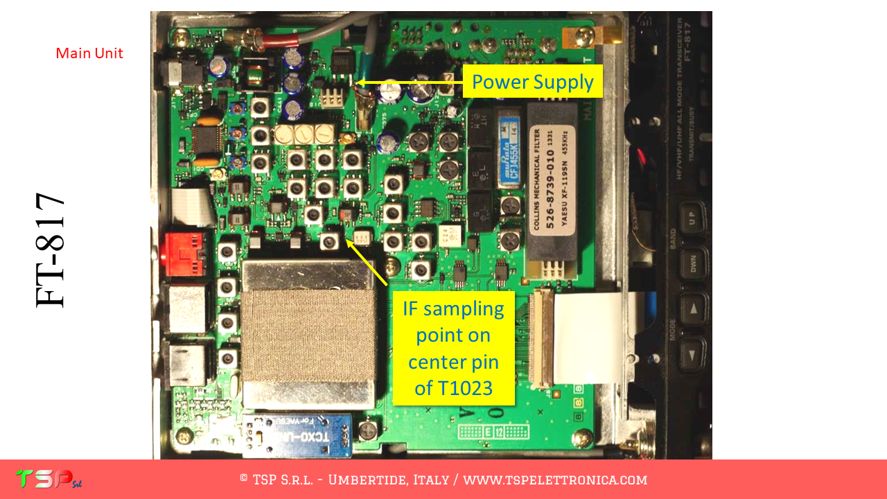
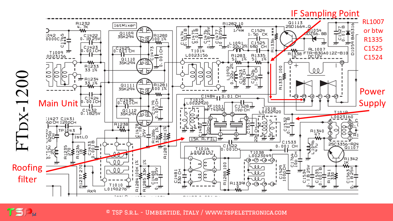
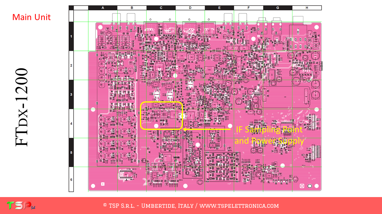
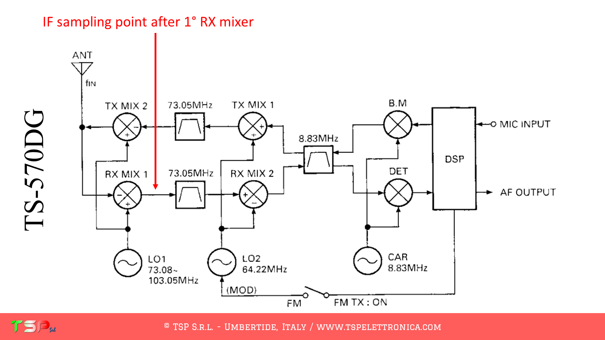
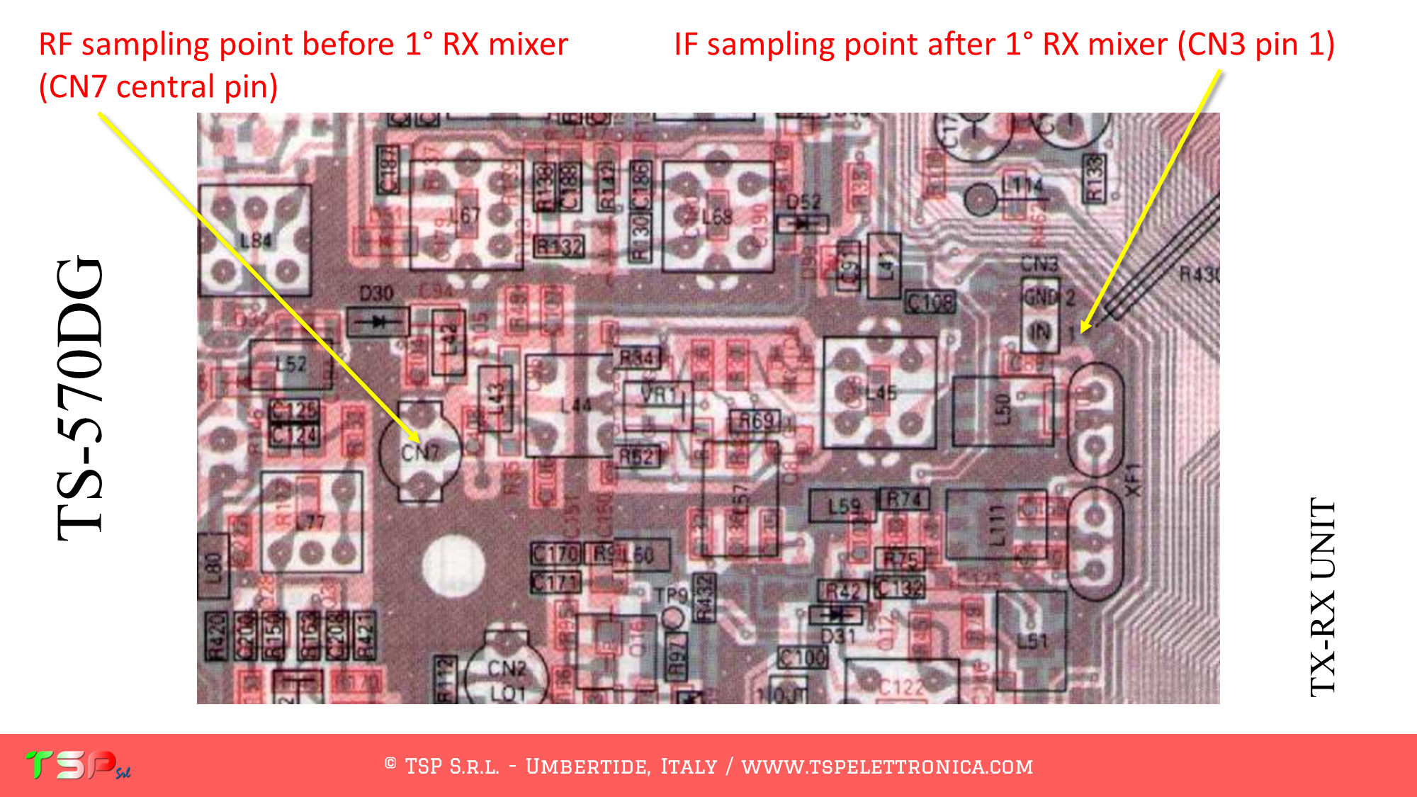
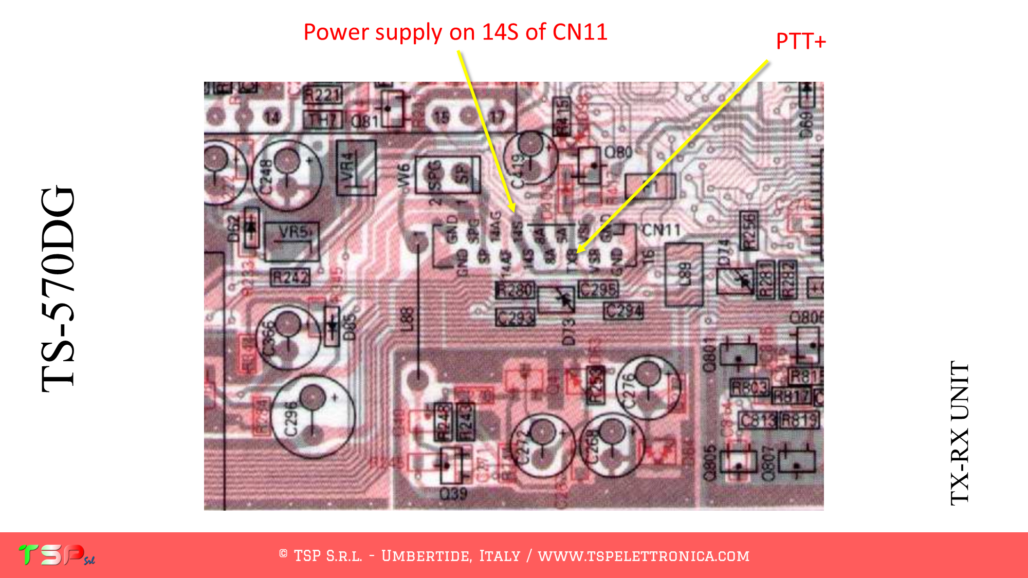
The TS-570D / G, like other radios, has a complex configuration and uses several intermediate frequencies. We are interested in having a “broadband” signal, so it will be picked up before the main band pass filter. The sequence of operations to be performed to obtain a sufficient bandwidth to create a panoramic receiver around the chosen IF frequency (73.05 MHz) is shown below. The path of the TX and RX signals is partly separate, so the PTT + signal to disable IFace during transmission is not strictly necessary but can help isolate the receiver during transmission. The following images show the point where to take the signals and the power supply.

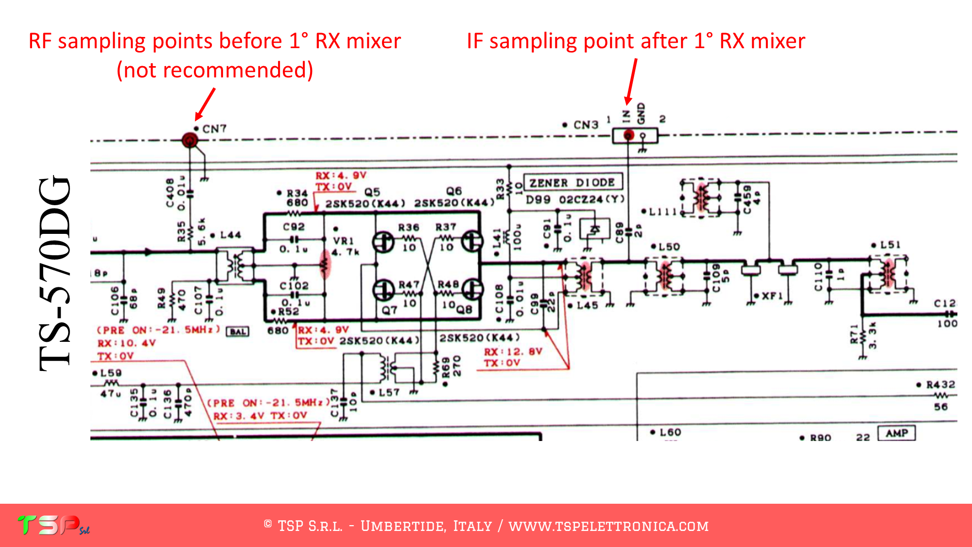
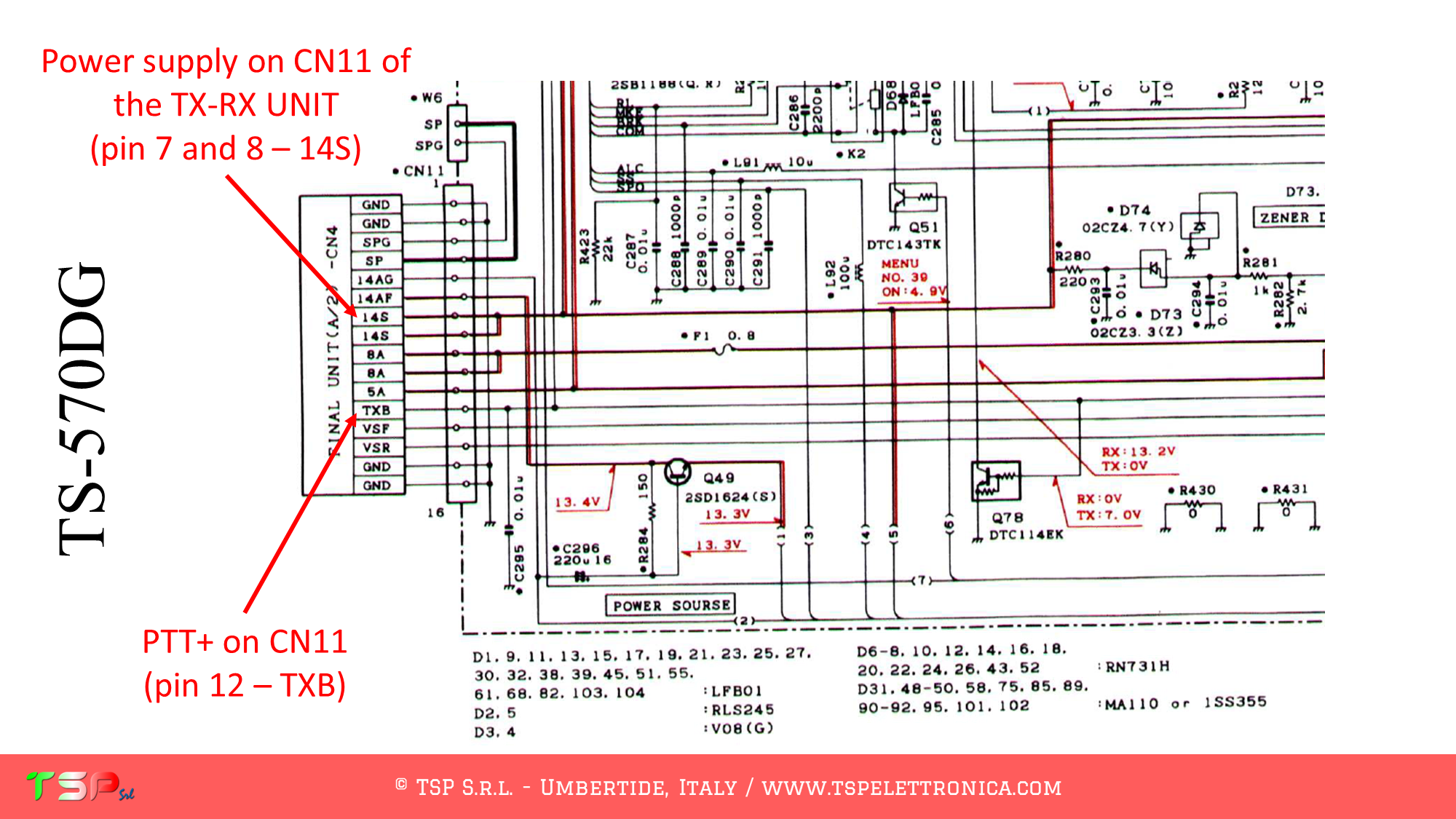
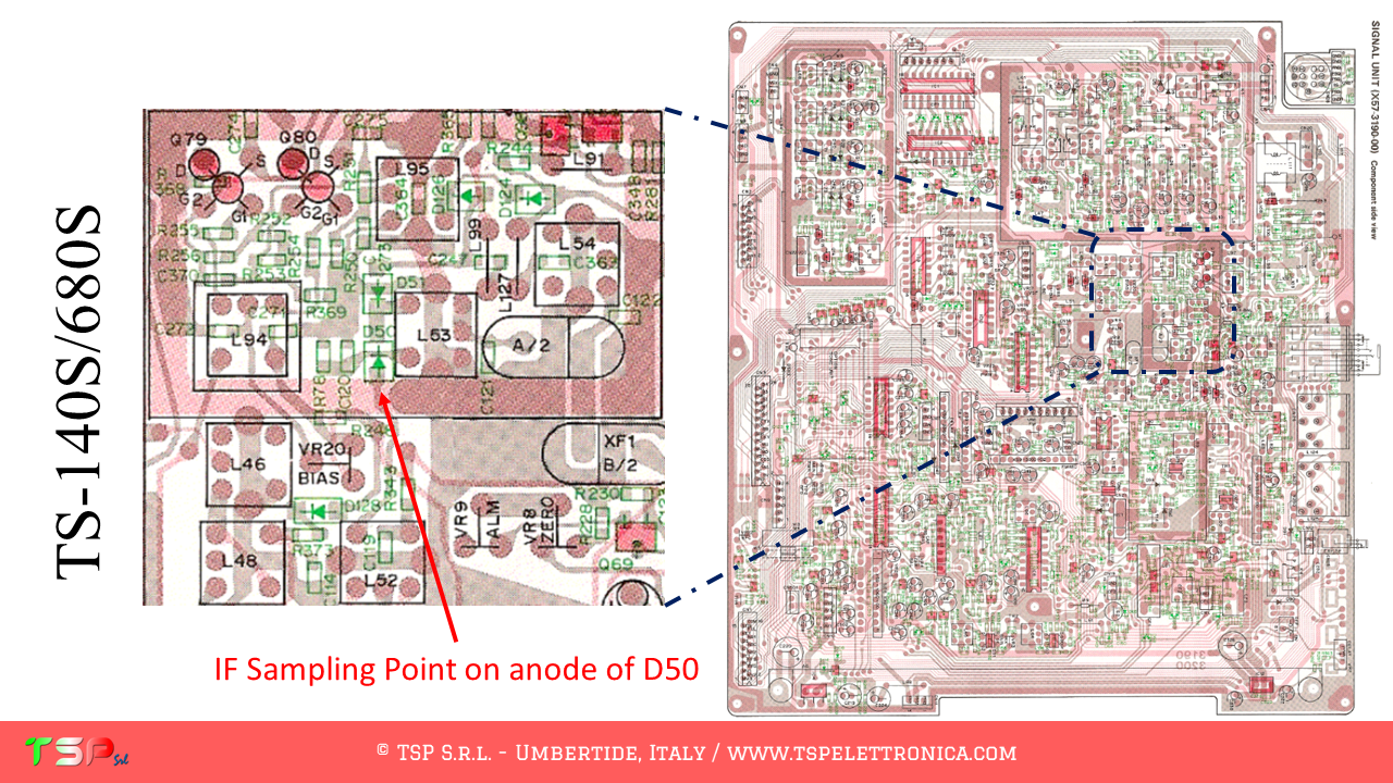
Now we need to locate the points where to connect the electric cables to the IFace. The following images illustrate where to get the various signals on the TX-RX UNIT.

If you like the idea and the goodness of the proposal buy an IFace using the buttons below.

Paypal

ATTENTION: Though installing the IFace is not difficult, you do this at your own risk. TSP S.r.l. is not responsible for any damage, unwanted side-effects or whatever.

For more information do not hesitate to write us.
Have fun!

SDR interface for the TS-590S

These are the instructions to install the IFace interface inside of the Kenwood TS-590S. The installation is very easy. For the TS-590SG see the note below.

IFace 2

The TS-590S, like other radios, has a complex configuration and uses different intermediate frequencies also depending on the band used. This radio requires 2 IFace cards because two intermediate frequencies are used, one at 11.374 MHz and another at 73.095 MHz. We are interested in having a “wide band” signal, so it will have to be taken before the main band pass filter.
The sequence of operations to be performed to obtain a sufficient bandwidth to realize a panoramic receiver around the chosen IF frequency is shown below. The path of the TX and RX signals is partly separate, so the PTT command to disable the IFace during transmission will not be necessary. The following images show the point where the IF signal will be taken.

As you can see below, the radio uses two different frequencies depending on the band chosen: it is therefore advisable to use two IFace interfaces and not to insert a mechanical switch.

Let’s start by analyzing the wiring diagram. We have to find the first mixer and where to take the power supply. From the following image everything will appear clear.

At this point we have to locate the points where we connect the electric cables to the IFace. The following images show where to take the various signals.

Last but not least, don’t forget to provide power supply to the IFace: you can easily find a source inside your radio.

NOTE ABOUT THE TS-590SG

If you like the idea and the goodness of the proposal buy an IFace using the buttons below.

Paypal

ATTENTION: Though installing the IFace is not difficult, you do this at your own risk. TSP S.r.l. is not responsible for any damage, unwanted side-effects or whatever.

For more information do not hesitate to write us.
Have fun!

SDR interface for the TS-140S/680S

These are the instructions to install the IFace interface inside of the Kenwood TS-140S/680S. The installation is very easy.

The TS-140S/680S, like other radios, has a fairly complex configuration and uses different intermediate frequencies. We are interested in the first (40.055 MHz), the “wide band” one, the one before the main band pass filter (the roofing filter so to speak). The sequence of operations to be performed in order to obtain a sufficient bandwidth to realize a panoramic receiver around the chosen IF frequency is shown below. The signal path for TX and RX are fairly separated, so to use the PTT command to disable the IFace during transmission is not required. The following images show the point where the IF signal will be taken.

Let’s start by analyzing the wiring diagram. We have to find the first mixer and where to take the power supply. From the following image everything will appear clear.

At this point we have to locate the points where we connect the electric cables to the IFace. The following images show where to take the various signals.

If you like the idea and the goodness of the proposal buy an IFace using the button below.

ATTENTION: Though installing the IFace is not difficult, you do this at your own risk. TSP S.r.l. is not responsible for any damage, unwanted side-effects or whatever.

For more information do not hesitate to write us.
Have fun!

SDR interface for the TS-450S and the TS-690S

These are the instructions to install the IFace interface inside of the Kenwood TS-450S/690S. The installation is very easy.

IFace 2

The TS-450S/690S, like other radios, has a fairly complex configuration and uses different intermediate frequencies. We are interested in the first, the “wide band” one, the one before the main band pass filter (the roofing filter so to speak). The sequence of operations to be performed in order to obtain a sufficient bandwidth to realize a panoramic receiver around the chosen IF frequency is shown below. The signal path for TX and RX are fairly separated, so to use the PTT command to disable the IFace during transmission is not required. The following images show the point where the IF signal will be taken.

Block diagram of the TS.-450S
Bloc diagram of the 1° mixer

Let’s start by analyzing the wiring diagram. We have to find the first mixer and where to take the power supply. From the following image everything will appear clear.

Electric diagram of the 1° mixer

At this point we have to locate the points where we connect the electric cables to the IFace. The following image shows where to take the various signals.

Layout of the RF UNIT

This last image shows the RF UNIT and where the IFace interface is to be connected.

Picture of the RF UNIT

If you like the idea and the goodness of the proposal buy an IFace using the button below.

Paypal

ATTENTION: Though installing the IFace is not difficult, you do this at your own risk. TSP S.r.l. is not responsible for any damage, unwanted side-effects or whatever.

For more information do not hesitate to write us.
Have fun!

SDR interface for the IC-706

These are the instructions to install the IFace interface inside of the Icom IC-706. The installation is very easy.

The IC-706, like other radios, has a fairly complex configuration and uses two different intermediate frequencies. We are interested in the first, the “wide band” one, the one before the main band pass filter (the roofing filter so to speak). The sequence of operations to be performed in order to obtain a sufficient bandwidth to realize a panoramic receiver around the chosen IF frequency is shown below. The intermediate frequency filter is also used in transmission, so it will be preferable to use the PTT command to disable the IFace during transmission. The following images show the point where the IF signal will be taken.

Let’s start by analyzing the wiring diagram. We have to find the first mixer, the PTT and where to take the power supply. From the following images everything will appear clear.

PTT and power supply can be easily taken from the connector J10. The interesting signal are labeled as T8 and 13.8 respectively.

At this point we have to locate the points where we connect the electric cables to the IFace. The following images show where to take the various signals.

This last image shows the inside of the RTX and where the IFace interface is to be placed.

If you like the idea and the goodness of the proposal buy an IFace using the button below.

ATTENTION: Though installing the IFace is not difficult, you do this at your own risk. TSP S.r.l. is not responsible for any damage, unwanted side-effects or whatever.

For more information do not hesitate to write us.
Have fun!

SDR interface for the IC-7600

These are the instructions to install the IFace interface inside of the Icom IC-7600. The installation is very easy.

The IC-7600, as well as other radios, has a fairly complex configuration and uses two different intermediate frequencies. We are interested in the first, the “wide band” one, the first one of the main band pass filter (the roofing filter so to speak). Below is the sequence of operations to be performed in order to obtain a sufficient bandwidth to make a panoramic receiver around the chosen IF frequency. Going over you can find some images that illustrate how to install the interface for SDR. The following image shows the point where the IF signal will be taken.

Let’s start by analyzing the wiring diagram. We have to find the first mixer, the PTT and where to take the power supply. From the following images everything will appear clear.

At this point we have to locate the points where we connect the electric cables to the IFace. The following images show where to take the various signals.

This last image shows the inside of the RTX and where the IFace interface is to be placed.

If you like the idea and the goodness of the proposal buy an IFace using the button below.

ATTENTION: Though installing the IFace is not difficult, you do this at your own risk. TSP S.r.l. is not responsible for any damage, unwanted side-effects or whatever.

For more information do not hesitate to write us.
Have fun!

SDR interface for the IC-756PROII

These are the instructions to install the IFace interface inside of the Icom IC-756PROII. The installation is very easy.

The IC-756PROII, as well as other radios, has a fairly complex configuration and uses three different intermediate frequencies. We are interested in the first, the “wideband” one, the first one of the main bandpass filter (the roofing filter so to speak). Below you can find some images that illustrate how to install the interface for SDR. The following image shows the point where the IF signal will be taken. The first IF frequency is 64.455 MHz.

Let’s start by analyzing the wiring diagram. We have to find the first mixer, the PTT and where to take the power supply. From the following images everything will appear clear.

At this point we have to locate the points where we connect the electric cables to the IFace. The following images show where to take the various signals.

This last image shows the inside of the RTX and where the IFace interface is to be placed.

To buy an IFace please one of the buttons below.

ATTENTION: Though installing the IFace is not difficult, you do this at your own risk. TSP S.r.l. is not responsible for any damage, unwanted side-effects or whatever.

For more information do not hesitate to write us.
Have fun!

SDR interface for the FT-897

Follow the steps below to install the IFace card in the YAESU FT-897. Installation is really very easy.

As always we start from the block diagram and try to find information on where to get the first intermediate frequency signal. We use the first because it is not filtered, i.e. the band is still wide. The following images make it very clear where this point is located. The PTT may not be necessary, the TX and RX circuits are well separated.

The power supply can be taken soldering a thin wire on the fuse F1001.

At this point all that remains is to identify the points on the PCB where to take the signals: refer to the following images.

If you are convinced of the goodness of the proposal buy an IFace using the button below.

WARNING: Although the installation of IFace is not difficult, it is done at your own risk. TSP S.r.l. is not responsible for any damage, unwanted side effects or anything else.

For more information do not exist to write to us.
Have fun!

SDR interface for the FT-817

Follow the steps below to install the IFace card in the YAESU FT-817. Installation is really very easy.

IFace 2

As always we start from the block diagram and try to find information on where to get the first intermediate frequency signal. We use the first because it is not filtered, i.e. the band is still wide. The following images make it very clear where this point is located. The PTT may not be necessary, the TX and RX circuits are well separated.

The power supply can be taken from the test point TP1084.

At this point all that remains is to identify the points on the PCB where to take the signals: refer to the following images.

If you are convinced of the goodness of the proposal buy an IFace using the button below.

Paypal

Testimonial IFace installation on the FT-818: click here!

WARNING: Although the installation of IFace is not difficult, it is done at your own risk. TSP S.r.l. is not responsible for any damage, unwanted side effects or anything else.

For more information do not exist to write to us.
Have fun!

SDR interface for FTDX1200

Follow the steps below to install the IFace card in the YAESU FTDX-1200. Installation is really very easy.

As always we start from the block diagram and try to find information on where to get the first intermediate frequency signal. We use the first because it is not filtered, i.e. the band is still wide. The following images make it very clear where this point is located. The PTT may not be necessary, the TX and RX circuits are well separated. The power supply can be taken from a point very close to the relais labeled RL1007.

At this point all that remains is to identify the points on the PCB where to take the signals: refer to the following images.

With the video below you can also view the instructions and listen to the explanations on how to install the IFace

In order to buy an IFace, please use the buttons below.

WARNING: Although the installation of IFace is not difficult, it is done at your own risk. TSP S.r.l. is not responsible for any damage, unwanted side effects or anything else.

For more information do not exist to write to us.
Have fun!

© TSP S.r.l. | VAT IT03137540542 | V.le Unità d'Italia 36, 06019 Umbertide, ITALY