These are the instructions to install the IFace interface inside of the Yaesu FT-780R in order to add an SDR panadapter to the radio. The installation is very easy.
After removing the cover, locate the electronic board called “MAIN UNIT”: the signal we are interested in are on this board.
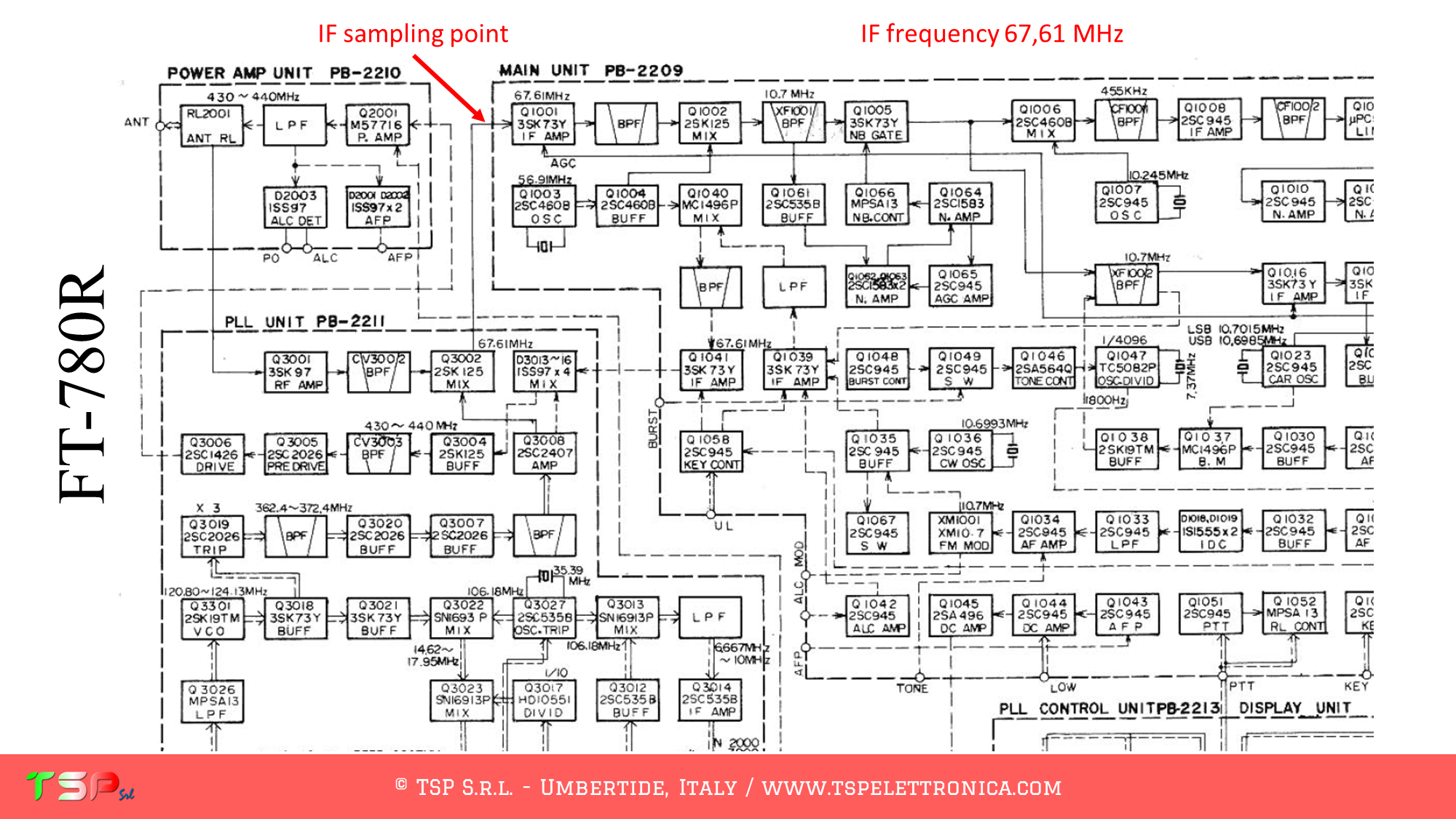
Refer to the following image of the wiring diagram to identify the points where you can weld the cables for the IF and the power supply. The PTT is not required, the signal paths are different for the RX and the TX.
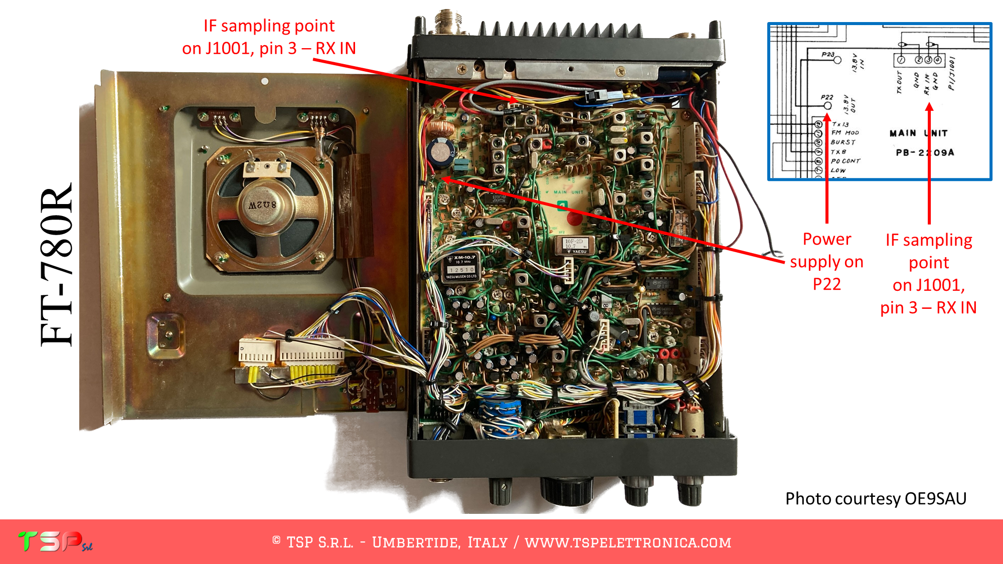
Refer to the following image to identify the points on the PCB where to weld the various connecting cables.
In order to buy an IFace please use the following buttons.
ATTENTION: Though installing the IFace is not difficult, you do this at your own risk. TSP S.r.l. is not responsible for any damage, unwanted side-effects or whatever.
For more information do not hesitate to write us. Have fun!
These are the instructions to install the IFace interface inside of the Yaesu FT-480R in order to add an SDR panadapter to the radio. The installation is very easy.
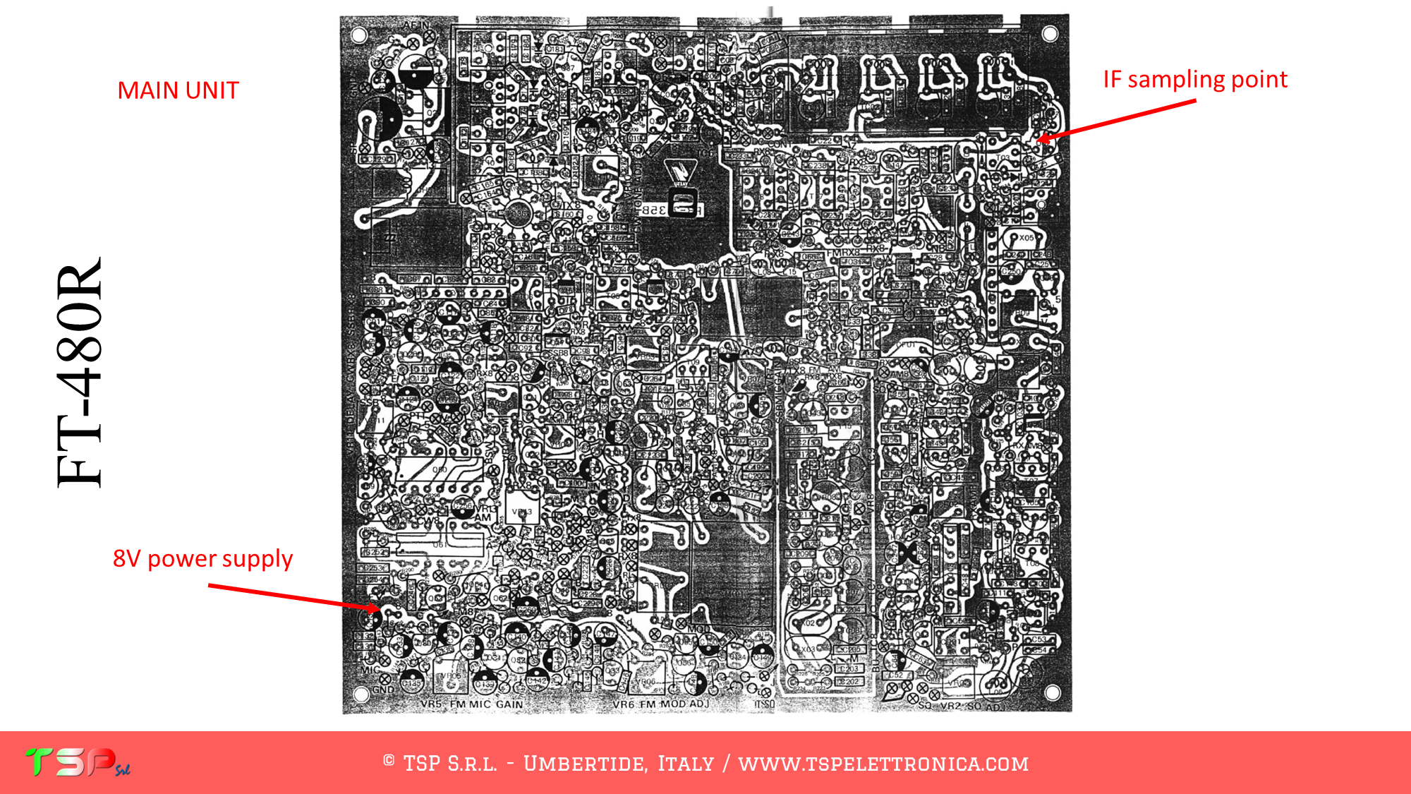
After removing the cover, locate the electronic board called “MAIN UNIT”: the signal we are interested in are on this board.
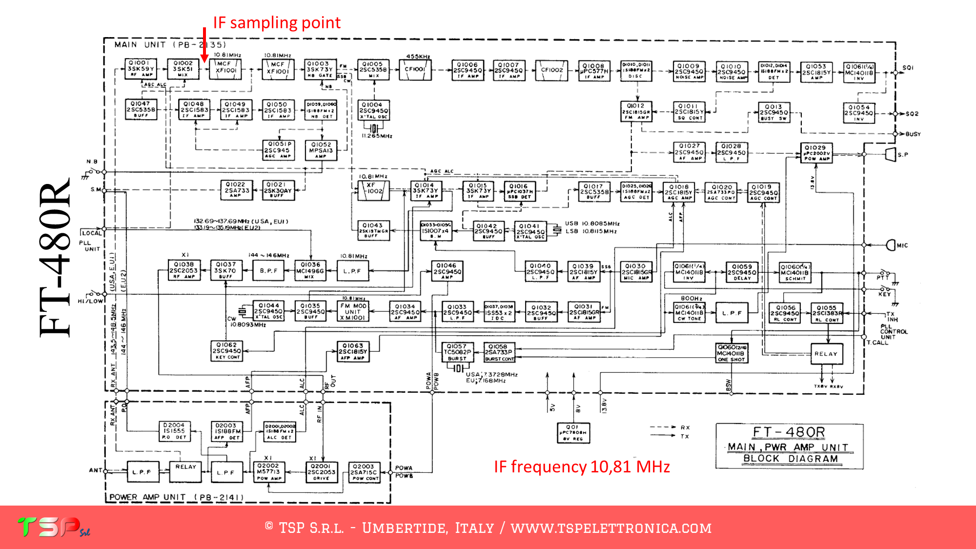
Refer to the following image of the wiring diagram to identify the points where you can weld the cables for the IF and the power supply. The PTT is not required, the signal paths are different for the RX and the TX.
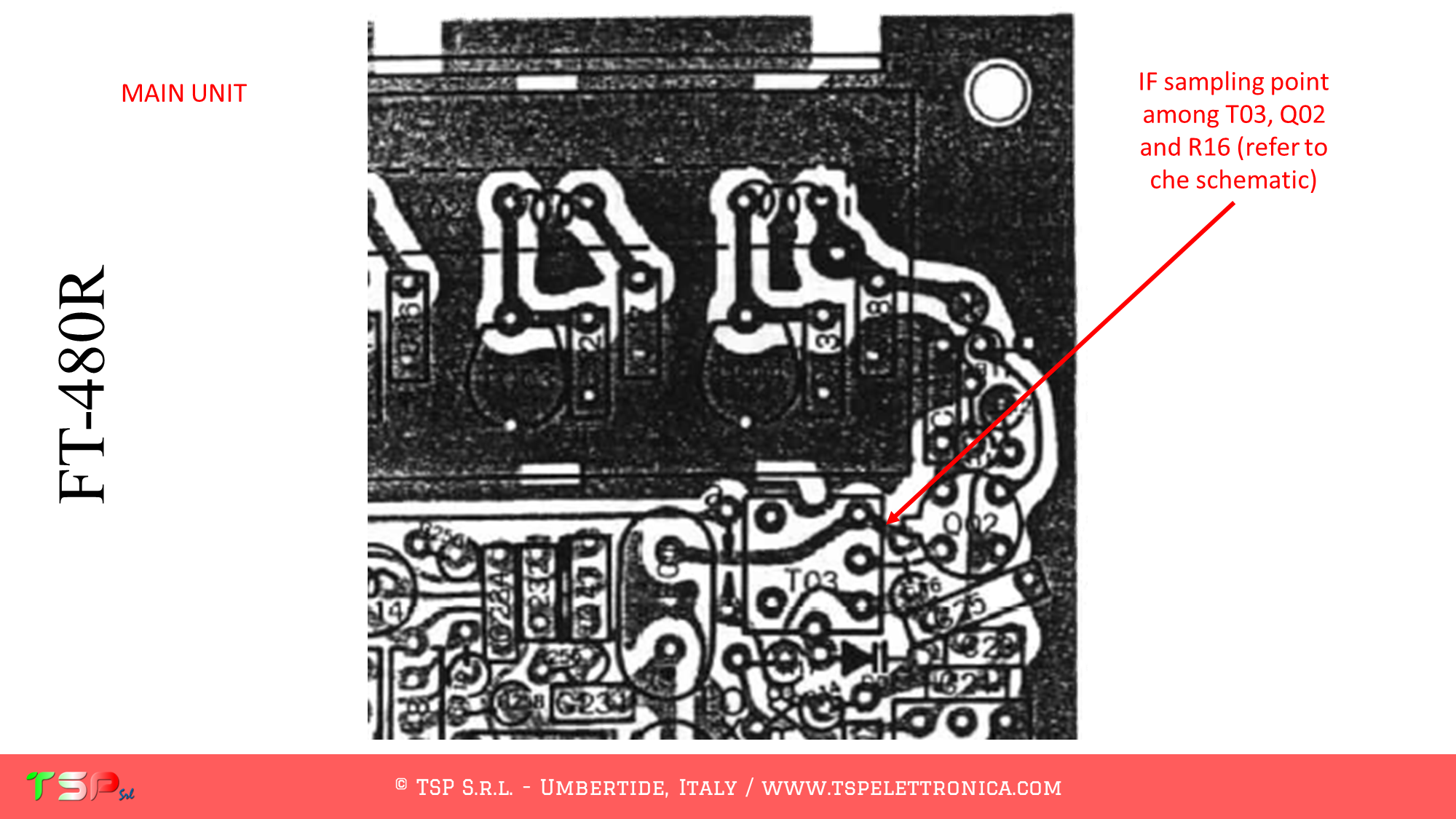
Refer to the following image to identify the points on the PCB where to weld the various connecting cables.
In order to buy an IFace please use the following buttons.
ATTENTION: Though installing the IFace is not difficult, you do this at your own risk. TSP S.r.l. is not responsible for any damage, unwanted side-effects or whatever.
For more information do not hesitate to write us. Have fun!
These are the instructions to install the IFace interface inside of the Kenwood R-2000 in order to add an SDR panadapter to the radio. The installation is very easy.
After removing the cover, locate the electronic board called “RX Unit”: the signal we are interested in are on this board.
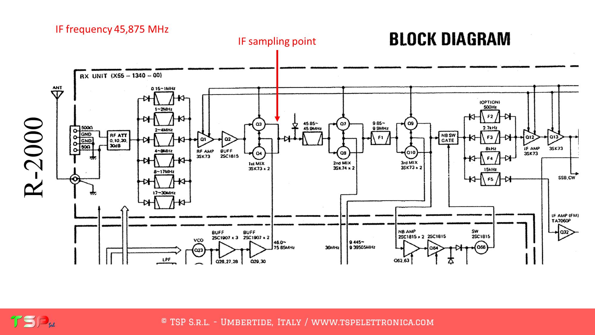
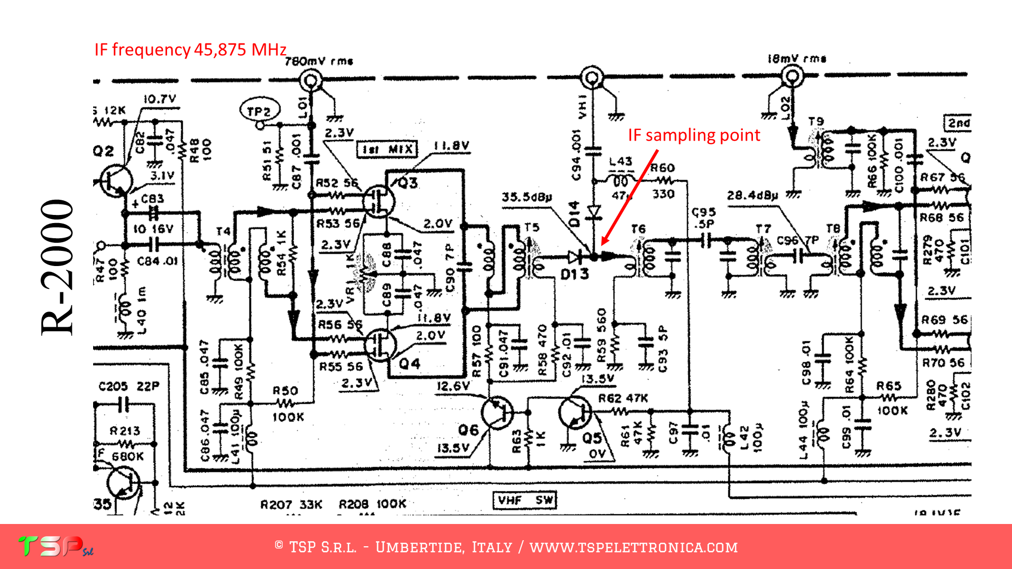
Refer to the following images of the wiring diagram to identify the points where you can weld the cables for the IF and the power supply. The PTT is not required, this is a receiver.
Refer to the following image to identify the points on the PCB where to weld the various connecting cables.
In order to buy an IFace please use the following buttons.
ATTENTION: Though installing the IFace is not difficult, you do this at your own risk. TSP S.r.l. is not responsible for any damage, unwanted side-effects or whatever.
For more information do not hesitate to write us. Have fun!
These are the instructions to install the IFace interface inside of the Kenwood TS-830s in order to add an SDR panadapter to the radio. The installation is very easy.
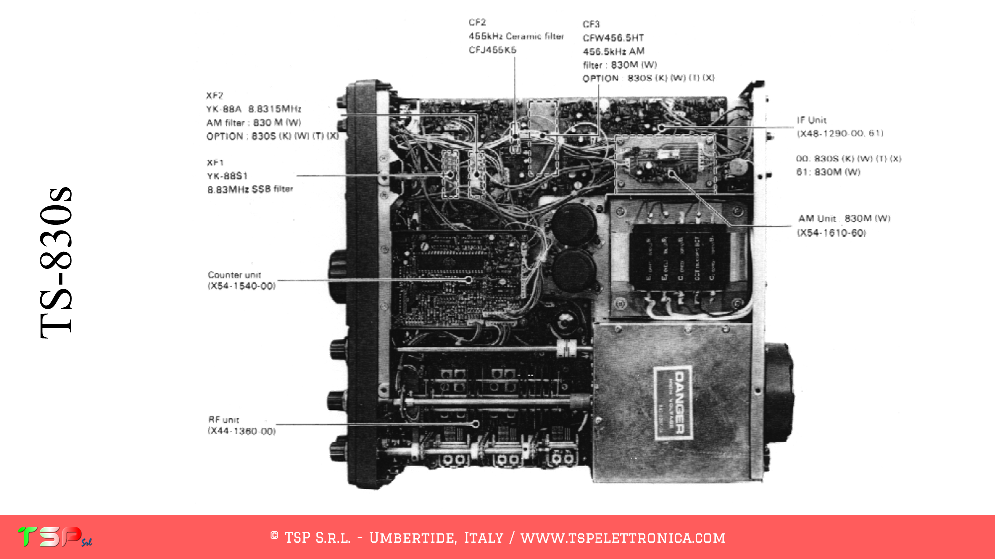
On the upperside of the radio, after removing the cover, locate the electronic board called “RF Unit”: this is shown in the following picture.
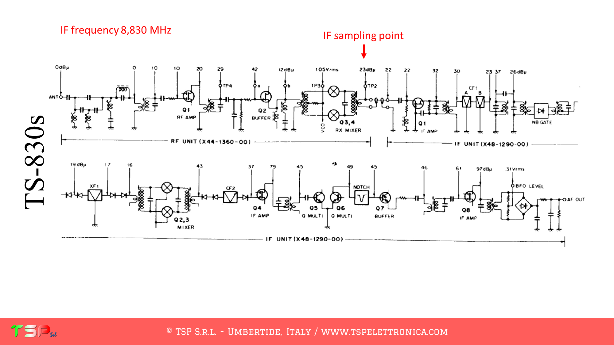
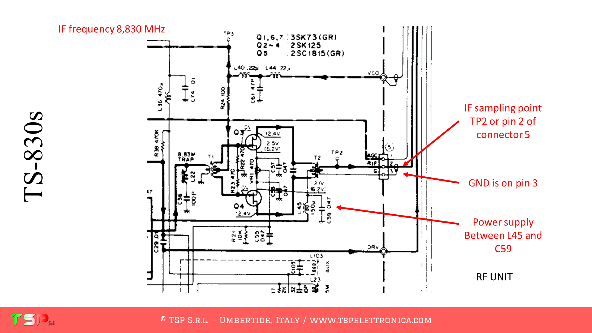
Refer to the following images of the wiring diagram to identify the points where you can weld the cables for the IF, power supply and PTT.
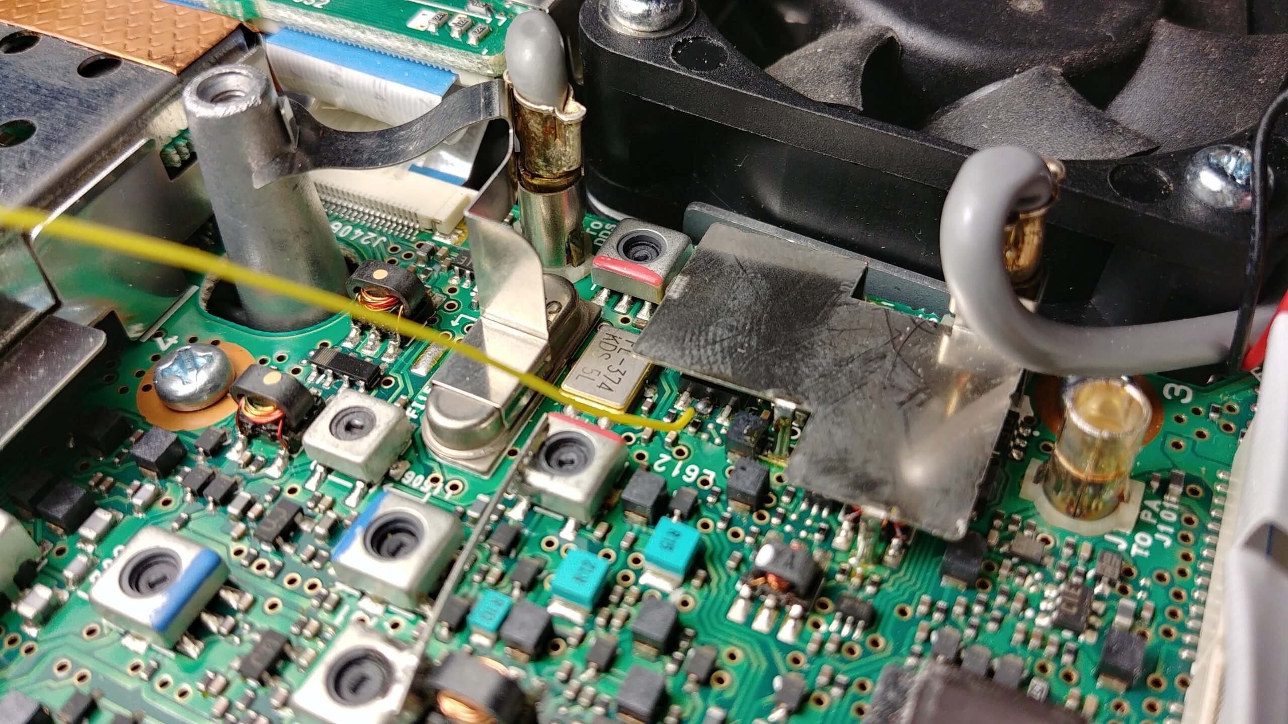
Refer to the following image to identify the points on the PCB where to weld the various connecting cables.
In order to buy an IFace please use the following buttons.
ATTENTION: Though installing the IFace is not difficult, you do this at your own risk. TSP S.r.l. is not responsible for any damage, unwanted side-effects or whatever.
For more information do not hesitate to write us. Have fun!
Our friend Gianni IK0AZG has installed our IF buffer interface IFace on his Icom IC-7000 in order to equip his radio with an SDR panadapter. The following photos show some details of the installation, specifically how the buffer interface was shaped in order to be placed in the very little space available inside the radio (also for this reason the smaller and thinner IFace 2 was then designed).
In this image you can see the point where the IF signal is taken through the yellow wire.In this image you can see the points where the power (positive red wire, negative black wire) and the IF signal (yellow wire) are taken.In this image you can see the IFace buffer board suitably shaped to reduce the overall dimensions and correctly positioned and wired to the radio.In this image you can see the output cable of the IF signal: it was chosen not to drill the rear panel of the radio and to use one of the openings on the back to pass the coaxial cable.
To purchase an IFace use one of the buttons below.
Thank you Gianni IK0AZG.
ATTENTION: Although the installation of IFace 2 is not difficult, it is done at your own risk. TSP S.r.l. is not responsible for any damage, unwanted side effects, or anything else.
These are the instructions to install the IFace interface inside of the Icom IC-706MKIIG. The installation is very easy.
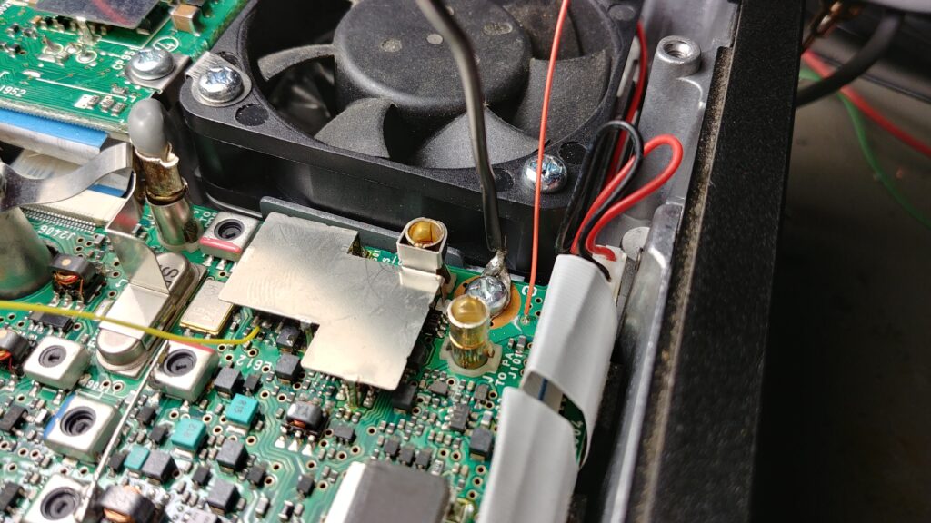
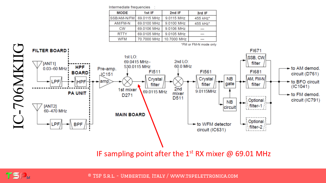
The IC-706MKIIG, like other radios, has a fairly complex configuration and uses two different intermediate frequencies. We are interested in the first, the “wideband” one, the one before the main bandpass filter (the roofing filter so to speak). The sequence of operations to be performed in order to obtain a sufficient bandwidth to realize a panoramic receiver around the chosen IF frequency is shown below. The intermediate frequency filter is also used in transmission, so it will be preferable to use the PTT command to disable the IFace during transmission. The following images show the point where the IF signal will be taken.
Let’s start by analyzing the wiring diagram. We have to find the first mixer, the PTT and where to take the power supply. From the following images everything will appear clear.
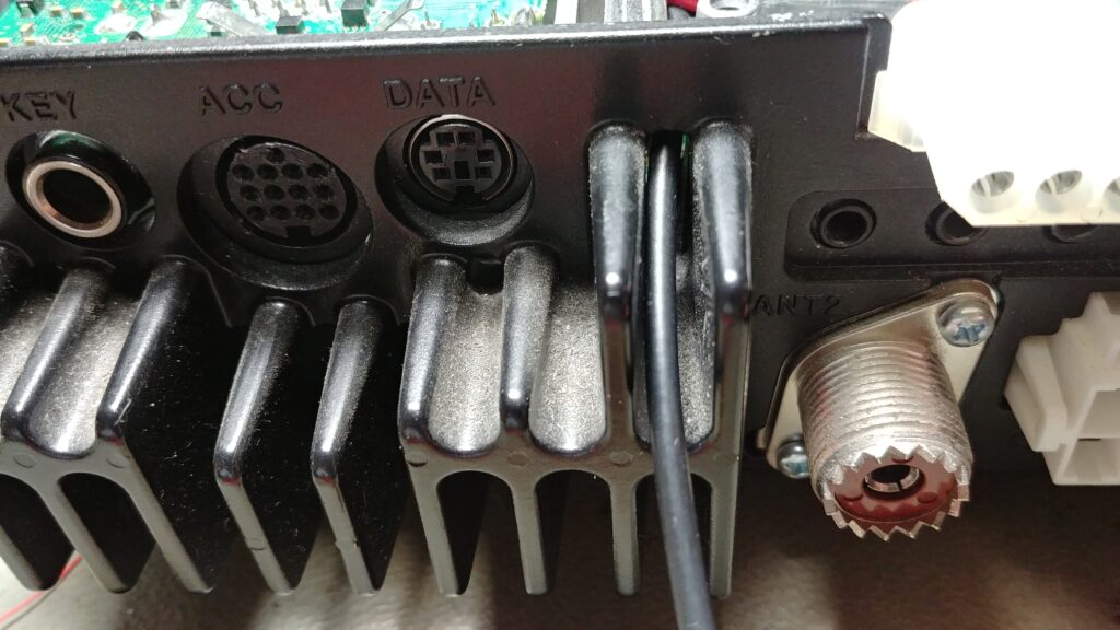
PTT and power supply can be easily taken from the connector J10. The interesting signal are labeled as T8 and 13.8 respectively.
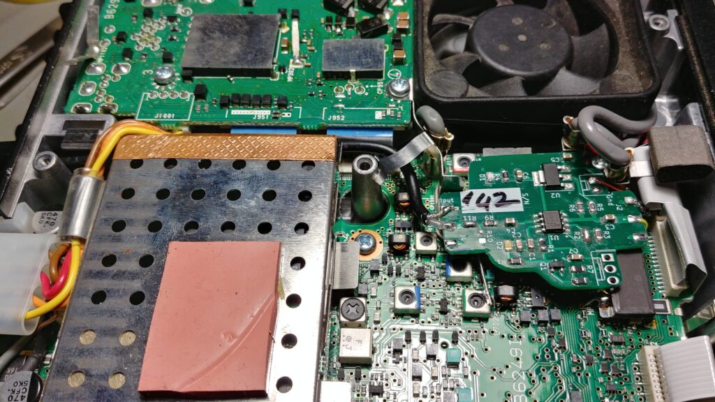
At this point we have to locate the points where we connect the electric cables to the IFace. The following images show where to take the various signals.
If you like the idea and the goodness of the proposal buy an IFace using the button below.
ATTENTION: Though installing the IFace is not difficult, you do this at your own risk. TSP S.r.l. is not responsible for any damage, unwanted side-effects or whatever.
For more information do not hesitate to write us. Have fun!
Would you like to have a radio with a nice 40 “LCD display where you can view spectrograms, waterfalls and much more information? And what would you say to have a modern SDR radio so that you can listen to more signals at the same time? Wouldn’t it be nice to have many digital filters to improve reception during contest or DX activity?
If you answered yes then IFace 2 is the electronic card that allows you to have all of this without having to buy a new radio. How? By inserting it inside your “old” beloved RTX and using a cheap SDR receiver (for example those with a USB port you can connect to your computer).
Don’t you think so? Please watch this video and then keep reading.
The idea behind this product is to continue to use the radio that we have purchased and which has already given us so much satisfaction. Surely we already have the CAT interface with which we control it from the LOG or from other programs and we also have the audio interface for the digital modes. But sometimes we realize that we would need a second receiver (for example to follow the +5 kHz or + 10 kHz of a DX station), band filters with steeper sides to eliminate a disturbance on an adjacent frequency or a notch because our radio does not have it or it is not automatic. All this can be a memory!
So suppose to send the intermediate frequency signal (IF) of our radio to a dedicated SDR receiver and to start a program such as HDSDR (or SDR #, SDR Console …). On the screen of our computer we would have the spectrum display around the IF of our radio and, not to be neglected, we could also demodulate what it is receiving. But we could do even more, we could also demoulate other signals that are above or below the frequency tuned by our RTX. Not bad, right? The image below shows a screenshot of HDSDR connected to an FT-450D via an RTL-SDR and the IFace.
Reception at the IF frequency of a FT-450D though the IFace and a RTL-SDR.
What needs to be done is very simple. Let’s start by identifying within our radio the point where to take the medium frequency signal. This is between the output of the first mixer and the subsequent bandpass filters as shown in the following image.
After connecting the IFace to the mixer output, we supply it with a voltage between 8 V and 15 V (from inside the radio) and connect it to an external SDR receiver. During the reception the difference is strong, listen here.
In order to not alter the operation of our receiver, we must pick up the signal without charging the mixer, i.e. without taking power. For this reason we have to insert a special card between this and the external receiver: we can not connect it directly. The IF signal pick up card, the IFace, creates a copy of the signal to be sent to the external SDR receiver. This is a wideband and no-tune buffer, i.e. no calibration is needed, it is installed and it is ready to work. The usefulness of this circuit is to allow the medium frequency signal to be replicated without increasing the load seen by the source (the mixer) and therefore without changing its performance.
Once the IF signal has been obtained, it is sufficient to connect the A / D converter (an RTL-SDR is already more than enough) to the USB port and start the software for the reception (ex HDSDR, SDR #, SDR Console etc) and our RTX will now be equipped with a nice panoramic receiver.
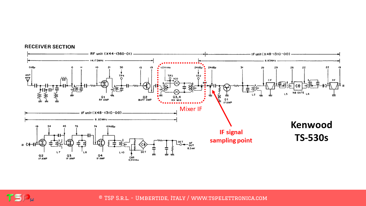
There are numerous advantages in picking up the IF signal and not the one coming directly from the antenna: one of these is surely the fact that the amplitude of the signal is controlled through the AGC circuitry of the reception stages. This helps to prevent saturation of the dynamics of RTL-SDR (which is not known to be the most extensive). The point where you take the IF signal is easy to find, just take the schematic diagram of your radio and look for the first mixer: at its output you will find the signal of interest. The image below shows the point where you have to connect the IFace interface in the case of a Kenwood TS-530s, a radio of a few decades ago, which can be easily updated with this interface.
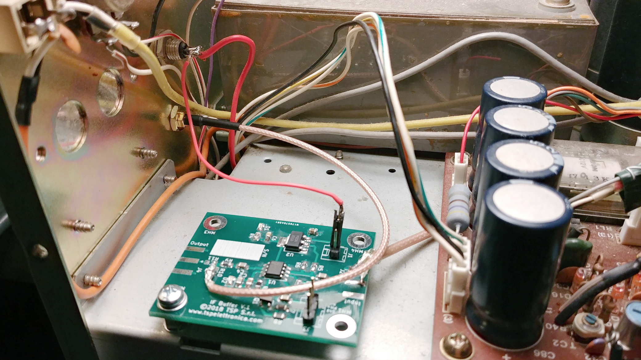
The connection to the chosen point can be made with a thin coaxial cable (type RG178 or RG316) and will terminate at the “Input” pad of the IFace. If the connection is very short, a coaxial cable may not be necessary. The “Output” instead will be connected with another small coaxial cable to the input of the chosen SDR receiver. Obviously the buffer must be powered: it will not be difficult to find inside the radio a point where to draw a voltage of 9 Vdc or 12 Vdc. The following images show how easy it is to install the IFace into the TS-530s.
Sampling point of the IF signalIFace inside a TS-530sIF output connectorPowering the IFace with 12 Vdc from the radio (red wire)Running IFace
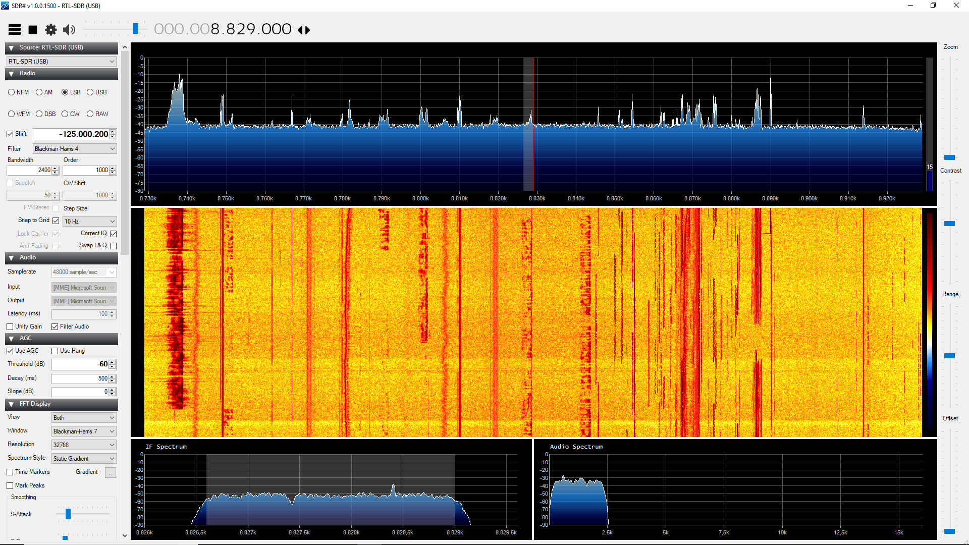
After making these simple wiring, you can connect your SDR receiver and start the reception software. The following image shows the SDR# screen during the reception with a Kenwood TS-530s (its intermediate frequency is 8.83 MHz) and an economical RTL-SDR.
Another IFace has been installed in a YAESU FT-450D. As you will see from the photos, the space occupied is very little and the time required to connect the 4 conductors (+13 V, Gnd, Ptt +, IF) is a few minutes. In this case the Ptt signal was used, that is the “TX” signal present in the IF-UNIT of the radio. All this clearly appears in the following images.
IFace Vs IFace 2: because the differences are important!
IFace
power supply: 8-15 Vdc, I <50 mA
bandwidth: > 700 MHz
input impedance: > 500 kOhm
output impedance: 50 Ohm
power-down input ( PTT)
dimensions: 38 x 48 mm, PCB 1.6 mm
IFace 2
power supply: 8-15 Vdc, I <50 mA
bandwidth: > 700 MHz
input impedance: > 1 MOhm
output impedance: 50 Ohm
power-down input ( PTT)
dimensions: 31 x 39 mm, PCB 0.8 mm
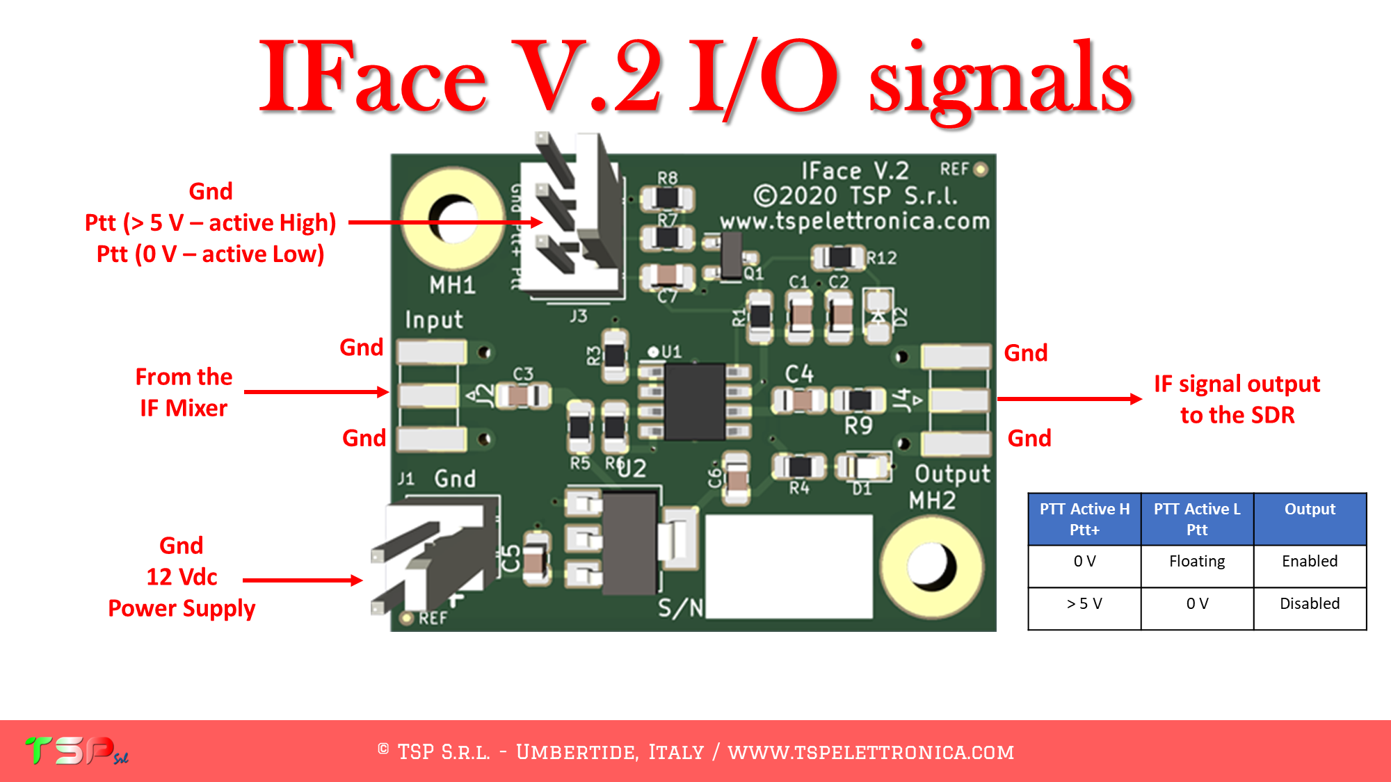
In case you do not want to display any signal during transmission it is possible to turn off, by sending it into power down, the buffer of the IFace through a special input pin (PTT) as shown in the following picture. To be more accurate, an active high PTT, i.e. the signal is at a voltage greater than 5 V when transmitting, otherwise 0 V, or an active low PTT, i.e. the signal is at 0 V when the radio is transmitting, otherwise it must be floating, can be used.
The following video shows how the card reacts to the pressure of the PTT, that is when the radio changes from reception to transmission: the red LED indicates that the card is in power-down because the radio is transmitting.
If you were still not convinced of the goodness of this interface look at this other video where you can see how the IFace works when added to an old Kenwood TS-530s.
Do you have any questions? Maybe we already have the answer you’re looking for.
The price of IFace 2 is only € 37.62 excluding VAT (€45,90 for EU customers) + shipments costs for the “IFace + Cables” kit.
If you also want the coaxial connectors, those for the power supply and those for the PTT buy the “IFace 2 + Connectors + Cables” kit.
In this page you can find thelist of the instructions to install the IFace into your radio: it is continuoursly growing. For those radios that are not included yet, send a request so that it can be entered as soon as possible.
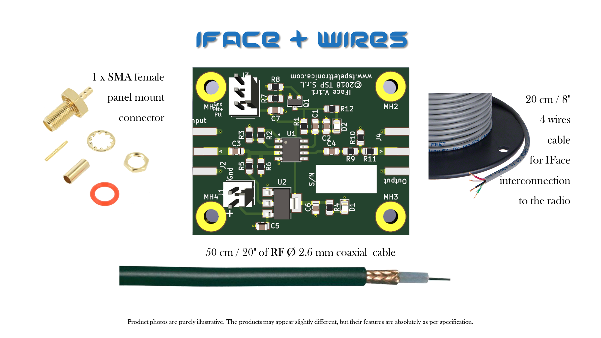
Content of the delivery “IFace + Cables”:
one IFace 2 board
a Ø 2.6 mm coaxial cable 50 cm / 20″ long to connect the output of the IFace to the signal output connector
one SMA female panel mount connector to be placed on the back of the radio
four wires to connect the board to the PTT, IF and powering points on the radio (colors of the wires may be subject to change)
Content of the delivery “IFace 2 + Connectors + Cables”:
one IFace 2 board
a Ø 2.6 mm coaxial cable 150 cm / 59″ long to connect the output of the IFace to the signal output connector (SMA female panel mount) and to make an interconnetion cable to the SDR receiver
one SMA female panel mount connector to be placed on the back of the radio
two SMA male connector to be crimped on the coaxial cable to connect the output connector to the SDR receiver
four wires to connect the board to the PTT, IF and powering points on the radio (colors of the wires may be subject to change)
2.54 mm pitch connectors for power and PTT
Order now by clicking on the following buttons and have fun.
ATTENTION: Though installing the IFace 2 is not difficult, you do this at your own risk. TSP S.r.l. is not responsible for any damage, unwanted side effects, or whatever.
If you have any questions, join the Telegram group dedicated to Amateur Radio by clicking here: Telegram Amateur Radio – English.
If you still have questions, use the following form, but don’t expect an immediate response, every day we receive many emails, including spam, so reading them is not a priority.
In a previous article we presented how to install the IFace card inside the Kenwood TS-2000 to obtain the IF signal of the HF and 50 MHz bands in order to send it to an external SDR. Now let’s see how to get the IF signal for the VHF and UHF bands. Installation is very easy.
The result you can obtain is well shown in the following video.
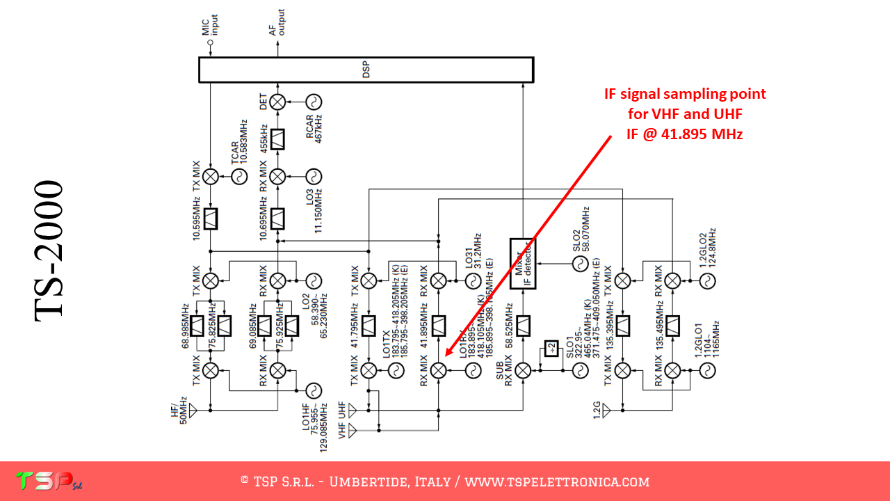
The TS-2000, like other radios, has a fairly complex configuration and uses different intermediate frequencies depending on the band on which you are operating. In any case, the one described here is the sequence of operations to be performed to obtain a bandwidth sufficient to provide a panoramic receiver around the IF frequency relative to the VHF and UHF bands.
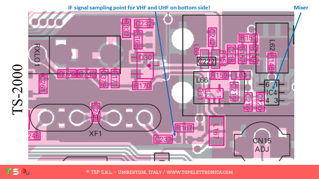
The point where the IF signal is taken can be identified more precisely using the electrical scheme as shown in the following images. The electronic card of interest is the one named TX-RX2 and the signal can be taken R167 or C233.
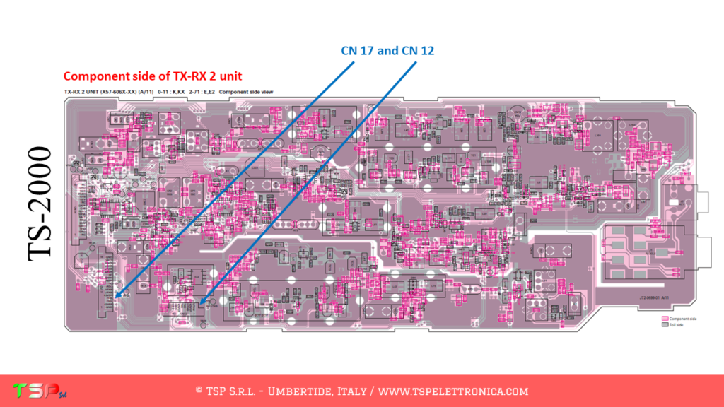
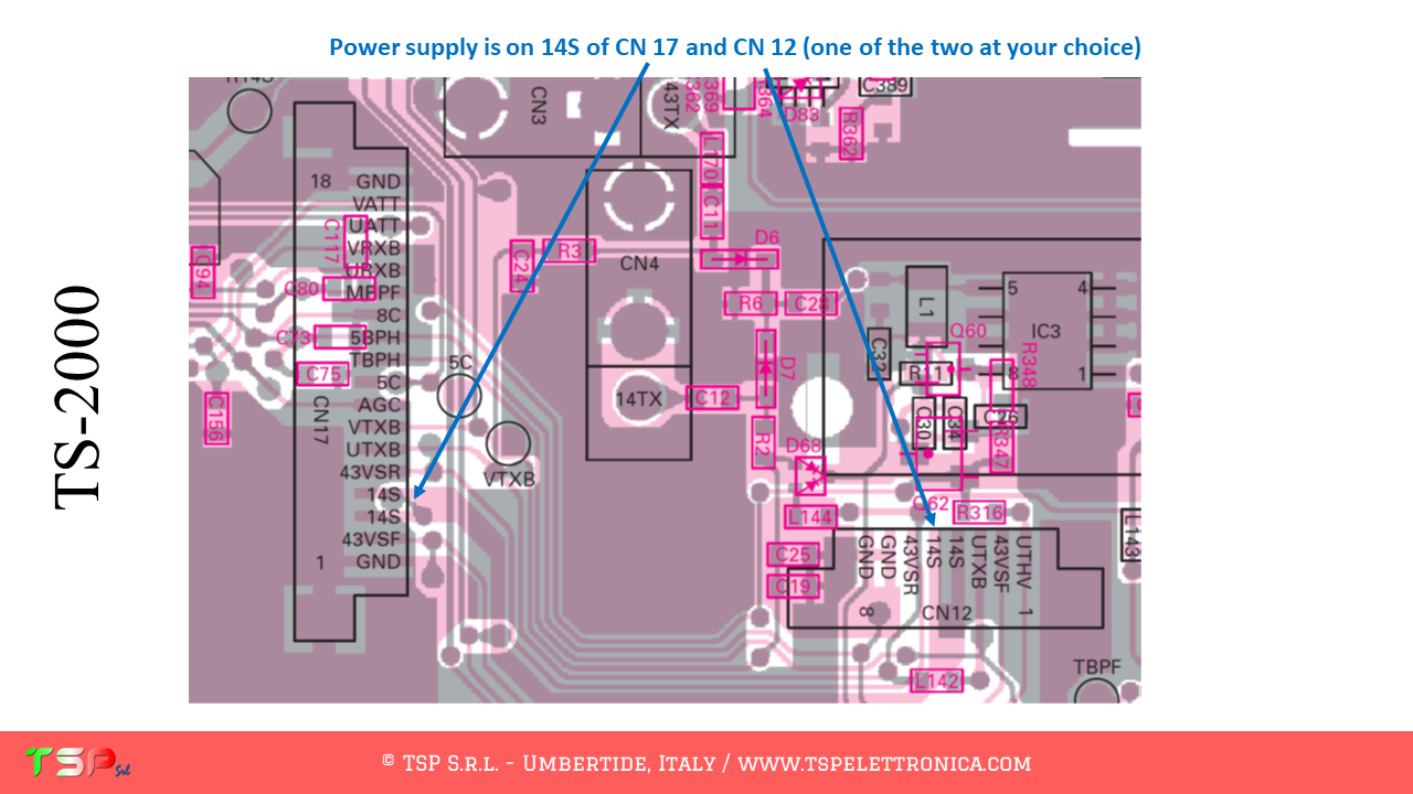
Now we need to find out where to get the power supply: energy can be taken from the CN 12 connector or from the CN 17, 14S signal.
PTT: for the TS-2000 it is not required because the reception circuit is automatically muted during transmission.
In the images that follow you can see the points where to take the IF signal: therefore the installation is really simple. Pay attention, for this RTX the IF sampling point is on the bottom layer of the TX-RX 2 UNIT.
You can by IFace 2 simply making click on the buttons below.
ATTENTION: Though installing the IFace is not difficult, you do this at your own risk. TSP S.r.l. is not responsible for any damage, unwanted side-effects or whatever.
For more information do not hesitate to write us. Have fun!
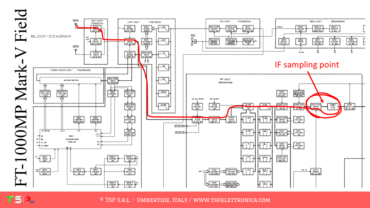
These are the instructions to install the IFace interface inside of the YAESU FT-1000MP Mark-V Field. The installation is very easy.
The FT-1000MP Mark-V Field, like other radios, has a very complex configuration and uses different intermediate frequencies. We are interested in having a “wide band” signal, so it will have to be picked up before the main band pass filter. The sequence of operations to be performed to obtain a sufficient bandwidth to realize a panoramic receiver around the chosen IF frequency (70.455 MHz) is shown below. The path of the TX and RX signals is partly separate, so the PTT command to disable the IFace during transmission will not be necessary. The following images show the point where the IF signal will be taken.
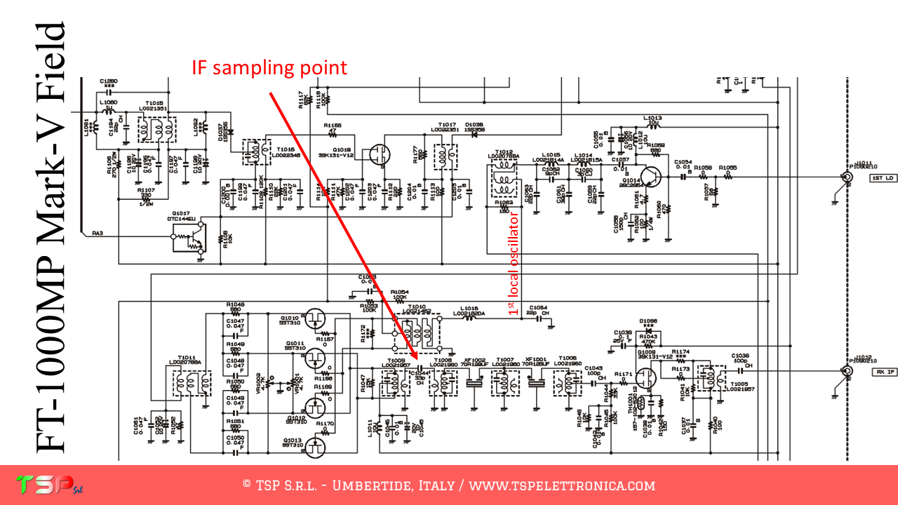
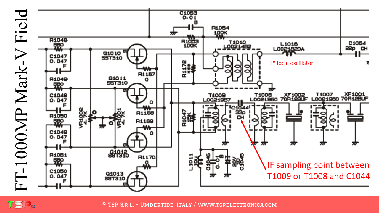
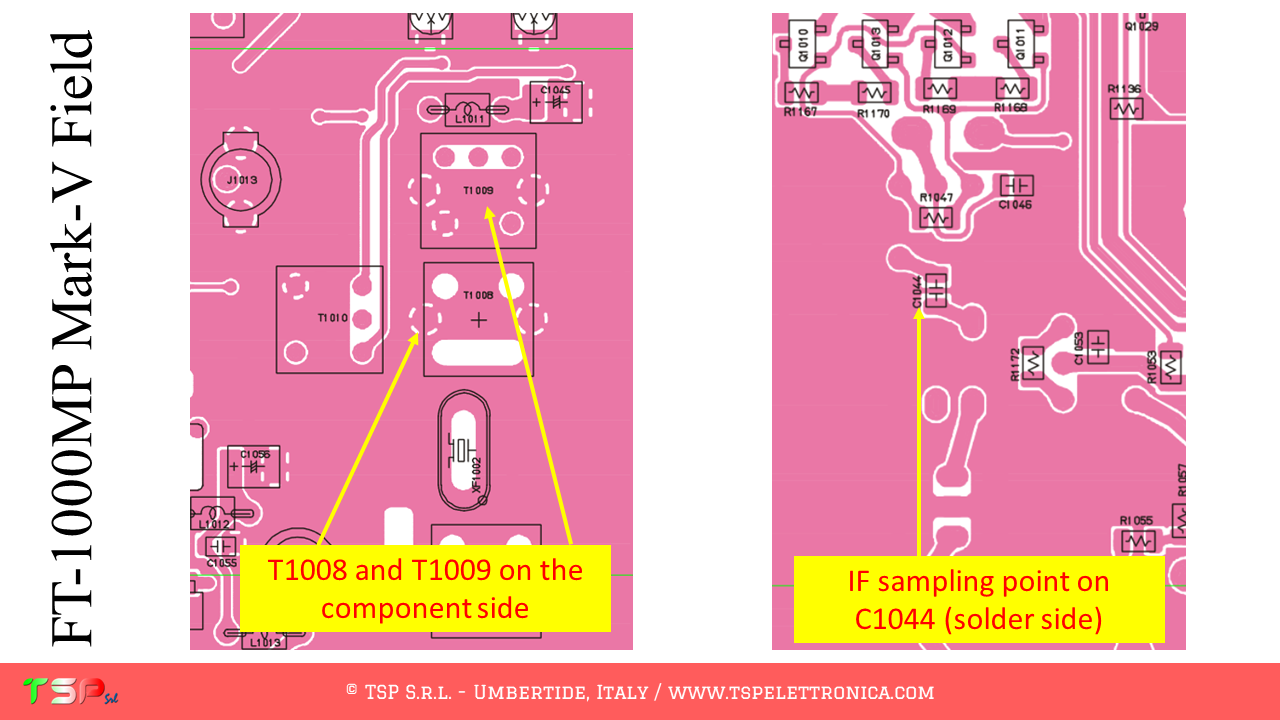
Now we need to locate the points where to connect the electric cables to the IFace. The following images illustrate where to get the various signals on the RF UNIT.
If you like the idea and the goodness of the proposal buy an IFace using the button below.
ATTENTION: Though installing the IFace is not difficult, you
do this at your own risk. TSP S.r.l. is not responsible for any damage,
unwanted side-effects or whatever.
For more information do not hesitate to write us. Have fun!
To install the IFace card inside the CODAN 9360 follow the steps below.
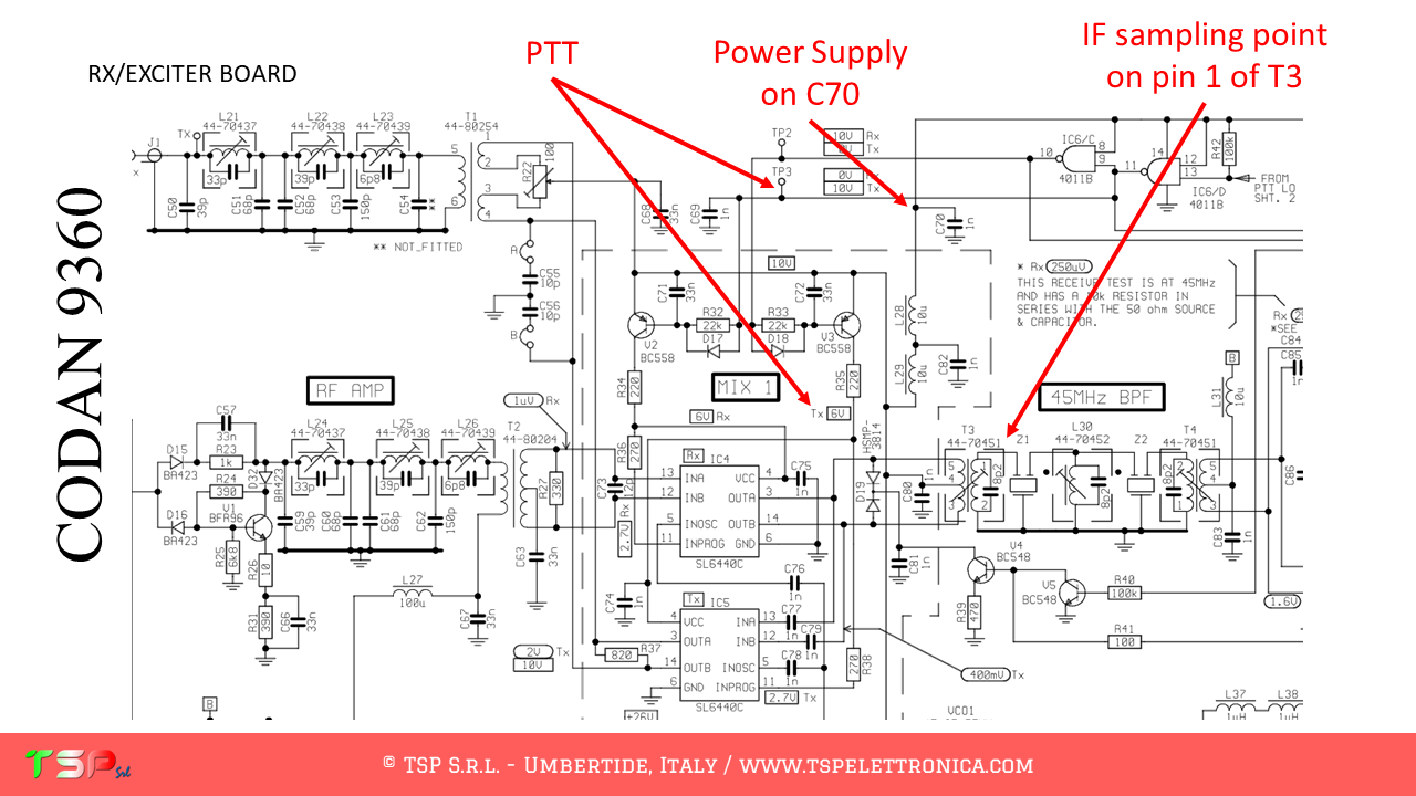
The CODAN 9360, like other radios, has a decidedly complex configuration and uses different intermediate frequencies. We are interested in having a “wide band” signal, so it will have to be picked up before the main band pass filter. The sequence of operations to be performed to obtain a bandwidth sufficient to realize a panoramic receiver around the chosen IF frequency (45 MHz) is shown below. The path of the TX and RX signals is partly separate, so the PTT command to disable IFace during transmission will be necessary. The following images show the point where the IF signal will be taken.
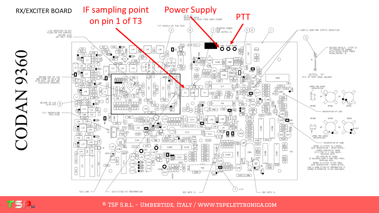
Now we need to locate the points where to connect the electric cables to the IFace: refer to the following image.
If you are convinced of the goodness of the proposal, buy an IFace using the button below.
WARNING: Although the installation of IFace is not difficult, it is done at your own risk. TSP S.r.l. is not responsible for any damage, unwanted side effects or anything else.
For more information, don’t hesitate to write to us. Have fun!
This website uses cookies to improve your experience. We'll assume you're ok with this, but you can opt-out if you wish.AcceptRead More
Privacy & Cookies Policy
Privacy Overview
This website uses cookies to improve your experience while you navigate through the website. Out of these, the cookies that are categorized as necessary are stored on your browser as they are essential for the working of basic functionalities of the website. We also use third-party cookies that help us analyze and understand how you use this website. These cookies will be stored in your browser only with your consent. You also have the option to opt-out of these cookies. But opting out of some of these cookies may affect your browsing experience.
Necessary cookies are absolutely essential for the website to function properly. This category only includes cookies that ensures basic functionalities and security features of the website. These cookies do not store any personal information.
Any cookies that may not be particularly necessary for the website to function and is used specifically to collect user personal data via analytics, ads, other embedded contents are termed as non-necessary cookies. It is mandatory to procure user consent prior to running these cookies on your website.
NEWS July 18, 2024 A Telegram group is now available through which you can interact to get faster responses from other customers or, if necessary, from TSP Srl.
Sign up for free by clicking here: Telegram TSP Customers.
Please limit the use of contact forms to send generic requests, they have low reading priority because they are often used to send spam.
NOVITA' 18 Luglio 2024
E' da oggi disponibile un gruppo Telegram tramite il quale interagire per avere risposte più veloci da altri clienti o, in caso, da TSP Srl.
Iscrivetevi gratuitamente facendo click qui: Telegram Clienti TSP.
Per favore limitare l'utilizzo dei form di contatto per inviare richieste generiche, hanno bassa priorità di lettura perché spesso usati per inviare spam.